bevel gears
Perform forged, cast and much less often bandaged. By the dimensions of the outer diameter, bevel gears can be made from several tens of millimeters to 2 ... 3 m. Due to the large range of dimensions, one gear design cannot be accepted. The manufacturing process and the force effect on the elements of the gear during the operation of the bevel gear also require different designs. The most common bevel gear designs are discussed below.
Choice of designs of bevel gears. Designs of bevel gears are selected according to Table. 10.
Here, as in cylindrical gears, the concepts of the smallest (d rp) and the largest Dgr boundary diameter of a bevel gear are introduced. The boundary diameters determine the design of the gear.
For gear wheels with a disk, when determining the boundary diameter, it is taken into account that holes with a diameter of at least 30 mm must be made in the disk. For this, a distance of 50 mm is required between the hub and the rim. The smallest boundary diameter must be: d rp = 100 + d cm + 2bsinφ. Thus, for d d > d r forged bevel gears must have the design shown on sheet 9, fig. 3, with d d ≤ d gr, the gear wheel is made without a disk (sheet 9, Fig. 2).
For large cast gears, the concept of the largest boundary diameter Dgp = dgp + 0.4L is introduced, which determines the design of cast bevel gears with four and six ribs.
In table. 10 shows the limits of the angle φ, which determines the shape of gears of various designs.
Determination of the dimensions of the elements of bevel forged gears. The formulas by which the dimensions of the elements of forged and cast bevel gears are determined are given in Table. eleven.
The main design is a gear wheel with a vertical disk without transverse ribs. This design provides strength and manufacturability.
Table 10
Choice of bevel gear design
Table 11
Formulas for determining the dimensions of elements of forged and cast bevel gears

Continuation of the table. eleven

Forged gears of small diameters are made without discs.
If, according to the design requirements or the strength conditions of the shaft, the diameter d is chosen so that the inequality
![]()
then the gear is made integral with the shaft (sheet 9, Fig. 4, 5) and is called the gear shaft.
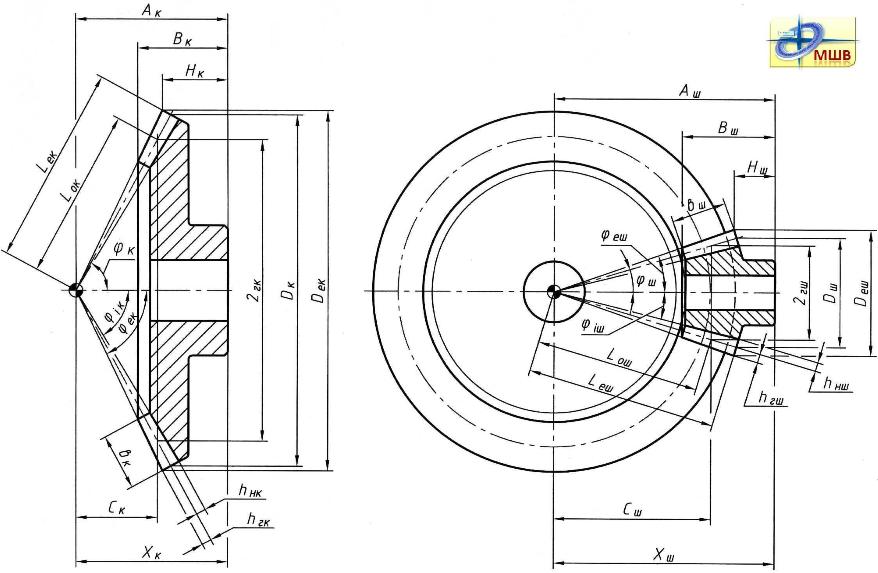
If, according to design requirements, the disk of a forged bevel gear must be placed at a certain distance from the ends of the hub (sheet 10, Fig. 1), then the hub should not protrude beyond the cone of the cavities, which is determined by the condition of cutting teeth on the machine.
In bevel gears made without holes in the disk and with a short protruding part of the hub, for the convenience of fixing the workpiece on the machine during turning from the end of the large cone, the tops of the teeth are cut along the diameter D cp with the following ratios between the mass of the workpiece and the length of the protruding cylindrical part hubs:
When cutting the tops of the teeth (sheet 9, Fig. 1.2), the diameter D cp is calculated at b cp = m. Then the resulting value D cp is rounded down and the width of the cut of the tops of the teeth b cp is determined by the formula
![]()
When cutting the tops of the gear teeth (sheet 9, Fig. 3) with an angle φ ≥ 45° (sheet 9, Fig. 2), the cut width b cp is determined by the same formula at D cp = d d.
Determination of the dimensions of the elements of cast bevel gears. The dimensions of the elements of cast gears depend not only on strength, but also on the necessary ratios between them, determined by the casting process. Depending on the dimensions, single-disk gears with four, six and eight ribs are produced. The choice of an even number of ribs is explained by the most favorable location of the profits and the elimination of defects in the form of shells, etc. The formulas for determining the dimensions of the elements of cast bevel gears are given in Table. 11. To calculate the rim thickness δ 0 of cast and forged bevel gears, the formula is adopted, as well as to calculate the thickness of the rim of cast cylindrical gears, taking into account the influence of the tooth width coefficient ψ ba and the total number of teeth z ∑ . In bevel gears, with a decrease in the angle φ, the value of the radial load increases and the distance from the point of application of this load to the axis of symmetry of the disk increases. To reduce the influence of moments from radial and axial loads, the distance l X from the end of the circle of the protrusions on the small cone to the disk is determined depending on the angle φ. In table. 11 shows the formulas for the preliminary determination of the hole in the wheel hub for the shaft. Taking into account the technology of casting in the places indicated by the letter N (sheet 10, Fig. 2, 3, 4), thickening of the rim to the height of the ribs is allowed. In the manufacture of forged and cast bevel gears, the same steels are used as for cylindrical gears.
Lecture #8
Bevel wheels are used in gears with intersecting shafts. Bevel wheels are made with straight, oblique, circular and other curved teeth. Currently, the most widely used conical wheels with circular teeth. Spur wheels are appropriate to use at low circumferential speeds (up to 8 m/s). At high speeds it is advisable to use wheels with circular teeth as they provide smoother engagement, greater bearing capacity and more technologically advanced.
Disadvantages of bevel gears:
1) manufacturing complexity;
2) the difficulty of adjusting the tooth contact patch;
3) relatively low efficiency. ( h to= 0,94…0,97).
The latter is explained by the fact that when the tops of the initial cones of the wheels do not coincide, the slip in the contact of the teeth increases sharply. In this regard, the design of the gearbox should provide for the possibility of adjusting the engagement of bevel gears.
Elements of geometric calculation
Shaft angle S, can be anything, but the most common angle is S=900. It's obvious that S=d1 +d2, Where d1 And d 2 - angles of dividing cones of the gear and wheel, respectively.
External taper distance Re determines the dimensions of the transmission (Fig. 8.1).
Working width of the ring gear b w can be expressed by the formula
b w \u003d y bd d m1 \u003d y bR R e ,
Where ybd- gear width ratio relative to its pitch diameter, - ring gear width ratio relative to the outer taper distance, d m- dividing diameter in the middle section.
 Instead of the initial and dividing cylinders of cylindrical wheels in bevel wheels, the concepts are introduced - the initial and dividing cones, which have the same properties as the dividing and initial cylinders. All dimensions of the gear are determined by the outer end:
h ae = m te - external height of the tooth head;
h fe = 1,2m t e is the outer height of the tooth stem;
mte– district module on the outer end;
df- the angle of the cone of the cavity of the teeth;
d a- the angle of the cone of the protrusions of the teeth;
d e =m te z is the diameter of the outer dividing circle;
d ae = d e +2h a cosd is the outer diameter of the protrusion circle;
d fe = d e -2h f cosd is the outer diameter of the circumference of the depressions.
The diameter of the pitch circle of a bevel gear is the diameter of the base of the pitch cone of the wheel. d e \u003d m te z \u003d 2R e sinδ, where
The dimensions of the tooth along the length are different, therefore, the concepts of diameter and modulus in the middle section are introduced:
![]()
![]()
![]() , Where R m is the average cone distance.
, Where R m is the average cone distance.
Gear ratio, because d e 1 = 2R e sind 1 And d e 2 = 2R e sind 2, That. For orthogonal transmissions in which S=90 0 , sin d 1 = cos d2 And U= tg d2= ctg d1.
Effort in engagement
 Let us consider the forces in engagement using the example of a bevel spur gear. We conditionally assume that all forces are applied in the middle of the tooth at diameters d m 1 And d m 2(see figure 8.3). In the section of the plane “ n-n” the normal tooth surface is affected by the full force F n, which is decomposed into a circumferential force F t and effort F r". In turn, the effort F r" in the frontal plane it decomposes into Fa(axial force) and F r(radial force). To determine all forces, the initial one is
through it efforts are determined

For a wheel, the direction of forces is opposite, while
![]()
Equivalent wheels and determination of their parameters
 The dimensions of the cross sections of the bevel gear tooth change in proportion to the distance of these sections from the top of the cone. All cross sections of the tooth are geometrically similar. At the same time, the specific load q(Fig. 8.4) is distributed unevenly along the length of the tooth. It varies depending on the magnitude of the deformation and the stiffness of the tooth in various sections according to the law of a triangle, the top of which coincides with the top of the dividing cone. Contact and bending stresses are the same along the entire length of the tooth. This allows you to calculate the strength for any of the sections. It is practically convenient to take for the calculated sections the average section of the tooth with a load q cf.
To calculate the strength, bevel wheels are replaced with equivalent cylindrical wheels, the dimensions of which are determined by the development of an additional cone j, in the middle section (Figure 8.5), while m tv = m tm.
Equivalent wheel diameter
![]()
Page 1
A circular tooth is located along the arc of a circle along which the tool moves when cutting teeth. The angle of inclination of the circular tooth is variable.
Circular teeth are usually made so that the tangent to the tooth line in the middle estrus A (Fig.
Circular teeth are cut by running on special high-performance machines with a cutter head.
Circular teeth in terms of strength differ from straight and helical teeth in their arc shape and initial contact at a point.
Circular teeth in terms of strength differ from straight and oblique teeth in an arc shape and initial contact at a point.
Circular teeth in terms of strength differ from straight teeth in their arc shape and initial contact at a point. The influence of these abilities is not well understood, however, based on experimental data, it has been established that bevel gears with circular teeth can transmit a load 145 times greater than spur bevel gears of the same dimensions.
Circular teeth can be used with taper distance L 6 - - - 420 mm.
A circular tooth is located along the arc of a circle, along which the tool moves when cutting teeth.
| Scheme for the geometric calculation of bevel gears.| Shapes of bevel gear teeth. |
Circular teeth are cut with a non-modular tool that allows cutting teeth in a certain range of modules. Therefore, it is allowed to use transmissions with non-standard and fractional modules.
Circular teeth in terms of strength differ from straight and helical teeth in their arc shape and initial contact at a point. Therefore, in the USSR and abroad, special calculations of bevel gears with circular teeth AGMA are widely used, developed by the Gleason gear cutting machine company, which has great experience design, manufacture and testing of bevel gears. These calculations have the same basis as those presented, but they also have some specific features.
A circular tooth is located along the arc of a circle, along which the tool moves when cutting teeth. The angle of inclination of the circular tooth is variable. The calculated angle is taken as the angle on the circumference of the average diameter of the wheel.
Spur bevel wheels are used at low circumferential speeds (up to 2 ... 3 m / s, up to 8 m / s is permissible). At higher speeds, it is advisable to use wheels with circular teeth, as they provide smoother gearing, less noise, greater bearing capacity and more technologically advanced. Spurs bevel gears provide a gear ratio of up to 3.
|
At peripheral speeds greater than 3 m / s, gears with oblique or curvilinear teeth, which, due to the gradual engagement and a smaller change in the amount of deformation of the teeth in the process of engagement, work with less noise and less dynamic loads. In addition, gear wheels oblique or curvilinear teeth work better in bending than spur teeth. However, for full contact of the teeth of these gears, the teeth must fit not only in their width, but also in height, which increases the requirements for the manufacture of helical gears and wheels with curved teeth. Due to their advantages, such gears can be used with gear ratios up to 5 and even higher. |
Figure 5 A) with straight teeth b) with oblique teeth V) with curved teeth G) bevel hypoid gear |
|
Figure 6 - The main elements of the teeth of bevel gears |
Bevel gears with oblique teeth can work with a peripheral speed of up to 12 m / s, and wheels with curvilinear teeth - up to 35-40 m/s. Gears with curved teeth cut in a spiral, involute (palloidal) or circle (circular) are most widely used. Bevel gears with curved teeth can have a different direction of the spiral. A gear wheel is called right-handed if the teeth are inclined outward in the direction of clockwise movement from the side of the top of the cone, otherwise the wheel is called left-handed. |

Correction of bevel gears
Used mainly high-altitude correction (correction) of conical wheels. Also used for bevel wheels tangential correction consisting in thickening of the gear tooth and thinning of the wheel tooth. Tangential correction of bevel wheels does not require special tools. For cylindrical wheels, tangential correction is not used, since it requires a special tool. In practice, for bevel wheels, height correction is often used in combination with tangential correction.
The teeth of the bevel gears, according to the change in the size of the sections along the length, perform three forms:
|
Figure 7 |
1. Normally lowering teeth. The vertices of the dividing and inner cones coincide. This form is used for bevel gears with straight and tangential teeth, and also limitedly for gears with circular teeth with mn>2 and Z = 20...100. |
Figure 8 |
2. The top of the inner cone is located so that the width of the bottom of the wheel cavity is constant, and the thickness of the tooth along the dividing cone increases with increasing distance to the top. This shape allows you to process both surfaces of the teeth of the wheel with one tool at once. Therefore, it is the basis for wheels with circular teeth. |
Figure 9 |
3. Equal high teeth. The generators of the dividing and internal cones are parallel. This shape is used for circular teeth with Z>40, in particular with average taper distances of 75-750 mm. |
Development computer programs for Designing Conical Pairs with Circular Tooth.
In the Repair (Single) production of Conical pairs with a Circular and Hypoid tooth, when taken as a basisavailable,but already worn, damaged and failed pairs, the calculation and determination of the geometric parameters does not require special tedious calculations for strength, load-bearing capacity, and operational stability. All this, at one time, at the stage of designing the Units and Machines for which they were intended, had already been carried out. Therefore, do not "bother" and waste time on this. Everything is limited by the selection of the appropriate material for the pairs and the type of their heat treatment. And this is solved simply - If you want something stronger, choose the appropriate material, cement, nitrid, harden. Not required - use ordinary ordinary structural steel. And sometimes, in general, the choice of material is limited by the capabilities of the enterprise at the moment - I would like it better, but not from anything. It's just that the primary task is to quickly and accurately reproduce the parameters of the pair and produce it with high quality.
Also in the Repair production, the issue of using a cutting shaping tool (Gear heads) used for cutting Conical pairs is being solved. Use the tool that they have. Therefore, in the calculations of the Geometrical parameters, the tool can also not be taken into account.attention.It, of course, will be recommended by the program, but it is finally determined and accepted already during further calculations of the corresponding Setup Charts.
So, the advantage of our programs: They don't require to work with thempreliminarytraining, with the involvement of relevant specialists. Programs during the dialogue, input of initial data, all the time they correct the user's actions, suggesting the boundaries of permissible values, which does not allow incorrect values to be entered, which ultimately lead to absurdity and a return to the beginning of calculations, as it happens in other proposed programs. They do not have unnecessary, as stated above, initial data, which takes a lot of precious time and ultimately confuses and does not give the necessary results (takes the calculations aside). At the same time, our programs give out a larger final calculated amount of information, including the layout and installation parameters of the calculated Bevel pairs with Circular and Hypoid teeth. What is of no small importance for their manufacture and performance.
Programs for the design of conical pairs
with Circular tooth Forms No. 1 and No. 2.
These programs allow you to enter when designingmandrels that take into account Western standards for gear pairs. That allows you to restore and calculate, from any worn and damaged gear pairs, all the geometric parameters necessary for their manufacture.
Form No. 1
Example of calculation by the program: