Detailed procedure for assembling the clutch yamz two-disk. Power transmission. Clutch
The assembly of the pressure kit should be carried out in the fixture shown in fig. 235 and under a hand press. The device consists of a stand having an installation dimension from the mating plane of the clutch cover to the plane of the pressure plate 27 ± 0.1 mm. In the center of the stand, a mandrel 8 is fastened with a bolt 7 to adjust the control size of the pressure set B (see ) equal to 64 ± 0.5 mm. In the mandrel there are four floating thrust crackers 6 (see Fig. 235).
When the pressure set is installed in the device, the biscuits rest against the tabs of the release levers 4 and, depending on their position, protrude or sink relative to the surface of the mandrel. The length of the mandrel is chosen in such a way that when it is installed on the release levers of the pressure set with a correctly adjusted reference size, the crackers are flush with the surface of the mandrel. The control dimension 64 ± 0.5 mm of the clutch pressure kit also includes the thickness of the thrust ring of the pull levers, which is 6 ± 0.1 mm, and since the pressure kit is adjusted in the device without a thrust ring, it must be adjusted to a size reduced by this value, i.e. by 58 ± 0.5 mm.
Assembly and adjustment is carried out in the following sequence:
- on the stand 11 of the device, the pressure disk is placed with the working surface down, fixing it with four spikes in the grooves of the stand;
- a needle bearing is inserted into the pull levers 4 (20 needles in each hole). The needles are placed on the CIATIM-201 lubricant or other grease corresponding to it;
- plugs 6 are installed on the pull levers (see Fig. 33);
- insert the axles of the forks;
- install the assembled levers in the grooves of the lugs of the pressure plate;
- insert the axis of the levers;
- put on the axis of the forks of the spring of the thrust ring;
- fix the axes of the levers and forks with special lock washers, bending the middle of the jumper of the apron;
- four loops 10 are put on the ends of the springs of the thrust ring 14;
- put pressure springs 20 on the bosses of the pressure disk, having previously placed washers with heat-insulating gaskets 21 under them.
When using a pressure plate machined along the working surface by 1 mm, a steel washer 1 mm thick is placed under each pressure spring 20 (from the side of the casing guide cups) to maintain the clutch pressure force.
Next, you need to put the clutch cover 19 on the guide pins of the fixture. All guide cups of the casing must enter the pressure springs, and the threaded shanks of the forks of the pull levers should enter the openings of the casing. Using a press, it is necessary to press the casing with the mating surface to the fixture and fasten it with bolts, then release it from under the press. Screw the adjusting nuts 3 onto the threaded shanks of the forks, install the mandrel to adjust the position of the pull levers 4 and secure it with bolt 7 (see Fig. 235) After that, adjust the position of the pull levers 4 with the adjusting nuts 3 so that they all simultaneously touch the stop crackers 16 of the mandrel 8, which must be flush with its upper surface. Thus, when installing the thrust ring, a control dimension is provided between the working surfaces of the pressure plate and the thrust ring.
Plates 2 are placed on the adjusting nuts 3, then the locking strips and the support plates of the forks of the levers, after which all eight locking bolts are wrapped. After tightening the bolts, the forks of the pull levers must not have axial play. The bolts are locked by bending the mustache of the locking bars. Having installed a thrust ring on the pull levers, fix it with loops so that it simultaneously touches the supporting surfaces of all four levers.
The runout of the end face of the thrust ring relative to the working surface of the pressure plate should not exceed 0.4 mm at a radius of 45 mm. Increased runout of these surfaces can lead to failure friction linings clutch disc and burns of the working surfaces of the flywheel and pressure plate.
.. 140 141 146 ..
CLUTCH YaMZ-238
CONSTRUCTION AND OPERATION OF THE CLUTCH
The clutch of the YaMZ-238 model is two-disc, dry, friction type, with a peripheral arrangement of cylindrical springs.
The casing 16 (Fig. 110) of the clutch, stamped from sheet steel, with the pressure plate 19 assembly is mounted on the flywheel 20 of the engine, and the driven discs 21 are mounted on the splined part of the gearbox input shaft.
The front and rear driven discs are installed in a specific position, as shown in the figure. The driven clutch discs are clamped by a constant force of cylindrical pressure springs 17 between the engine flywheel, the middle and pressure discs. Under the springs on the side of the pressure plate are placed heat-insulating
gaskets 18. The pressure and middle driving disks are connected to the flywheel with four spikes located on the outer surface of the disks. When clamped, the driven disks transmit the engine torque to the input shaft of the box
gears.
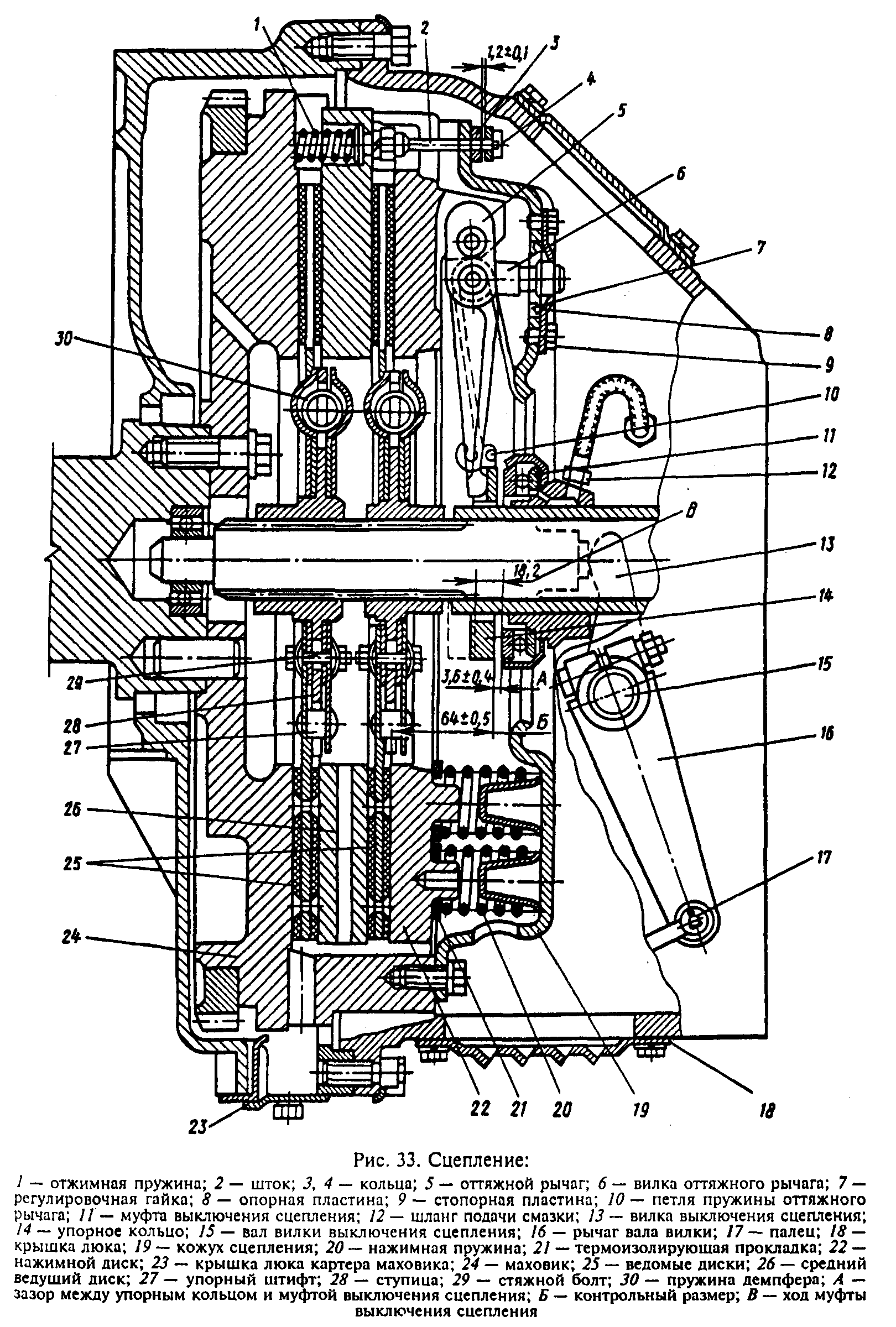
Rice. 110. Clutch YaMZ-238:
1-rod; 2-ring; 3-cup spring; 4-bar; 5-pull lever; 6-fork of the retractable lever; 7-adjusting nut; 8-base plate; 9 stop plate; 10-loop spring release lever; 11-clutch release clutch
with bearing; 12-hose for supplying lubricant to the clutch release clutch; 13- clutch release switch; 14-thrust ring of pull levers; 15-shaft of the clutch release fork; 16-clutch cover; 17-pressure spring; 18- heat-insulating gasket; 19-pressure disc; 20 flywheel; 21-slave drives; 22-medium drive disc; 23-pressure spring;. D-minimum travel of the release clutch
The clutch is disengaged by clutch 11. The clutch with the bearing, moving towards the engine, removes the pressure plate from the driven disk, transferring force through four rigid pull levers 5. The working stroke of the clutch release clutch, taking into account the free play, must be at least 18.2 mm (size "D"). The amount of free play is controlled by the clutch release mechanism. The thrust ring of the pull levers moves towards the gearbox by 27 mm due to the allowable wear of the friction linings.
Guaranteed gaps between the driven disks and the friction surfaces of the flywheel, the middle drive and pressure plates when the clutch is turned off as the linings wear out are provided by the mechanism for automatically adjusting the offset of the middle drive, which consists of rods 1 fixed in each of the four spikes of the middle drive drive, split rings 2, which require a certain force to move along the rod, thrust strips 4, which are bolted to the flywheel with the clutch cover, and Belleville springs 3, mounted on the rod between ring 2 and strip 4.
When the clutch is disengaged, the pressure disk 19 moves back by at least 2 mm, and releases the rear driven disk 21. The middle drive disk 22 under the action of the spring 23 also moves back, until the ring 2 stops against the bar 4 through the belleville spring, by a value of 1, 2±0.1 mm, releasing the front driven disc.
As the friction linings of the clutch wear out, the middle driving disk moves to the flywheel under the action of the pressure springs of the pressure disk, while the rings 2 abut against the clutch cover, moving along the rods 1 and maintaining the size between the rings and Belleville springs. When the pads of the driven disks are worn, the end face of the clutch release clutch will rest against the end face of the bearing cover of the input shaft of the gearbox; in this case, replace the worn linings of the driven disks with new ones.
Clutch YaMZ-238N- double-disk, dry, friction type, with a peripheral arrangement of cylindrical springs. Clutch YaMZ-238N can be made sealed.
Cover 16 ( rice. 6) clutch, stamped from sheet steel, with pressure plate 19 as an assembly mounted on the flywheel 20 engine, and the driven disks 21 - on the splined part of the input shaft of the gearbox. The front and rear driven discs are not interchangeable and are installed in a specific position, as shown in the figure. The driven clutch discs are clamped by a constant force of twenty-eight cylindrical pressure springs 17 between the engine flywheel, the middle and pressure discs. Thermal insulating pads 18 are placed under the springs on the pressure plate side. The pressure and middle driving discs are connected to the flywheel with four spikes located on the outer surface of the discs. When clamped, the driven discs transmit the engine torque to the gearbox input shaft.
Rice. 6. Clutch YaMZ - 238N: 1 - rod; 2 - ring; 3 - disc spring; 4 - strap; 5 - pull lever; 6 - fork of the pull lever; 7 - adjusting nut; 8 - spacer plate: 9 - locking plate; 10 - spring loop of the pull lever; 11 - clutch release with bearing; 12 - lubricant supply hose to the clutch release clutch; 13 - clutch release fork; 14 - thrust ring of pull levers; 15 - clutch release fork shaft; 16 - clutch cover; 17 - pressure spring; 18 - thermal insulating gasket; 19 - pressure plate; 20 - flywheel; 21 - driven disks; 22 - middle driving disk; 23 - release spring; D - minimum stroke of the release clutch.
The clutch is disengaged by clutch 11. The clutch with the bearing, moving towards the engine, removes the pressure plate from the driven disk, transferring force through four rigid pull levers 5. The working stroke of the clutch release clutch, taking into account the free play, must be at least 18.2 mm (size "D"). The amount of free play is controlled by the clutch release mechanism. The thrust ring of the pull levers moves towards the gearbox by 27 mm due to the allowable wear of the friction linings.
Guaranteed gaps between the driven disks and the friction surfaces of the flywheel, the middle drive and pressure plates when the clutch is turned off as the linings wear out are provided by the mechanism for automatically adjusting the offset of the middle drive, which consists of rods 1 fixed in each of the four spikes of the middle drive drive, split rings 2, which require a certain force to move along the rod, thrust strips 4, which are bolted to the flywheel with the clutch cover, and Belleville springs 3, mounted on the rod between ring 2 and strip 4.
When the clutch is disengaged, the pressure disk 19 moves back by at least 2 mm, and releases the rear driven disk 21. The middle drive disk 22 under the action of the spring 23 also moves back, until the ring 2 stops against the bar 4 through the belleville spring, by a value of 1, 2 ± 0.1 mm, releasing the front driven disc.
As the friction linings of the clutch wear out, the middle driving disk moves to the flywheel under the action of the pressure springs of the pressure disk, while the rings 2 abut against the clutch cover, moving along the rods 1 and maintaining the size between the rings and Belleville springs.
When installing a clutch with a mechanism for automatically adjusting the withdrawal of the middle disc to the flywheel, observe the following procedure:
- Install the front driven disc.
- Install the middle driving disc with rods.
- Install the rear driven disc.
- Install the pressure plate and housing assembly by securing it to the flywheel with eight short bolts.
- Push the split rings 2 onto the rods 1 as far as they will go into the clutch cover.
- Push on the four Belleville springs with the convex side towards the split rings.
- Install four thrust bars and secure them with the casing to the flywheel with eight long bolts.
After installing the clutch on the flywheel, make sure that the rings on the rods are against the casing, providing a gap of 1.2 ± 0.1 mm between the rings and the Belleville springs when the clutch is engaged.
When the pads of the driven disks are worn, the mountaineer of the clutch release clutch will rest against the end of the bearing cover of the input shaft of the gearbox; in this case, replace the worn linings of the driven disks with new ones.
The lack of free play of the clutch release clutch will lead to failure of the pressure bearing and increased slippage of the driven discs. The free play of the clutch release clutch (dimension “A”) is regulated by changing the length of the release mechanism rod or the length of the booster cylinder rod, depending on the design of the clutch release mechanism, in accordance with the instructions in the vehicle operating instructions.
Attention! It is strictly forbidden to adjust the clutch release clutch free play with the adjusting nuts of the release levers.
After adjustments, check the clutch for lack of "leading"; This test must be carried out with the engine running, in first gear and the clutch disengaged.
Adjustment of the position of the thrust ring of the pull levers
When assembling the pressure plate with the casing assembly, adjust the position of the thrust ring. This adjustment should be made in a fixture having an installation dimension of 27 ± 0.1 mm ( rice. 7) adjusting nuts 6 of the pull levers with a fixed position of the casing and the pressure plate, by adjusting to ensure the dimension "B" equal to 64 ± 0.1 mm, while the thrust surfaces of all four pull levers 5 must simultaneously touch the thrust ring 4. The misalignment of the thrust ring will lead to uneven withdrawal of the pressure plate when the clutch is turned off or its abnormal operation.
Rice. 7. Device for assembling the pressure plate with the cover assembly: 1 - stand; 2 - guide pin; 3 - a bolt of fastening of a casing; 4 - thrust ring of pull levers; 5 - pull lever; 6 - adjusting nut; 7 - locking plate; 8 - base plate; 9 - pressure plate.
After adjusting the position of the thrust ring with adjusting nuts 6, install the locking 7 and support 8 plates of the adjusting nuts. Screw in all eight bolts securing the lock and base plates, installing spring washers under the bolt heads.
In the case of using a pressure plate with a casing complete with driven discs after repair, on which friction linings with a thickness of 4.15 mm are installed, when adjusting the position of the thrust ring, set the dimension “B” to 67 ± 0.1 mm.
Array ( => Array ( => Checkout => /info/ => => R => Array () => D => 0 => Array () => 1 =>) => Array ( => Payment = > /info/payment/ => => R => Array () => D => 1 => Array () => 1 =>) => Array ( => Delivery => /info/delivery/ => = > R => Array () => D => 2 => Array () => 1 =>) => Array ( => Warranty => /info/warranty/ => => R => Array () => D => 3 => Array () => 1 =>) => Array ( => News => /info/news/ => => R => Array () => D => 4 => Array () => 1 =>) => Array ( => Stocks => /info/sale/ => => R => Array () => D => 5 => Array () => 1 =>) => Array ( => Articles => /info/articles/ => 1 => R => Array () => D => 6 => Array () => 1 =>) => Array ( => Q&A => /info/faq/ => => R => Array () => D => 7 => Array () => 1 =>) => Array ( => Manufacturers => /info/brands/ => => R => Array() => D => 8 => Array () => 1 =>) => Array ( => Parts catalogs
and assembly units => /info/catalogs/ => => R => Array () => D => 9 => Array () => 1 => 1 => Array ( => Array ( => MMZ => /info/catalogs/mmz/ => => R => Array () => D => 0 => Array () => 2 =>) => Array ( => MTZ => /info/catalogs/mtz/ => => R => Array () => D => 1 => Array () => 2 =>) => Array ( => YaMZ => /info/catalogs/yamz/ => => R => Array() => D => 2 => Array() => 2 =>))))
Technical parameters of YaMZ-238 clutch
Maximum engine torque, Nm. - 920
Mass of rotating parts, kg - 70
Moment of inertia of the driven disk, kg.m2 - 0.09 x 2
Driven disk slot dimensions, mm - 42x34x6
YaMZ-238, YaMZ-236 clutches differ only in the number of pressure springs. The YaMZ-238 clutch can be made in a sealed version.
The casing 16 (Fig. 1) of the YaMZ-238 clutch of the MAZ-5516, MAZ-64229, 6303 and Kraz-255, 6510, Kraz-65101 vehicles, stamped from sheet steel, with a pressure plate 19 assembly is mounted on the flywheel 20 of the engine, and driven disks 21 - on the splined part of the input shaft of the gearbox.
The front and rear clutch discs YaMZ-238 are interchangeable and are installed in a certain position, as shown in the figure.
The driven clutch discs are clamped by a constant force of cylindrical pressure springs 17 between the engine flywheel, the middle and pressure discs.
The YaMZ-236 clutch has eighteen pressure springs, YaMZ-238 clutch- twenty springs. Under the springs on the sides of the pressure plate, thermally insulating gaskets 18 are placed.
The pressure and middle driving discs of the YaMZ-238 clutch are connected to the flywheel with four spikes located on the outer surface of the discs.
When clamped, the driven discs transmit the engine torque to the gearbox input shaft.
The YaMZ-238 clutch is disengaged by clutch 11. The clutch with the bearing, moving towards the engine, removes the pressure plate from the driven disc, transferring force through four rigid pull levers 5.
The working stroke of the YaMZ-238 clutch of the MAZ-5516, MAZ-64229, 6303 and Kraz-255, 6510, Kraz-65101 vehicles, taking into account the free play, must be at least 18.2 mm (dimension "D").
The amount of free play is controlled by the clutch release mechanism. The thrust ring of the pull levers moves towards the gearbox by 27 mm due to the allowable wear of the friction linings.
Guaranteed gaps between and the friction surfaces of the flywheel, the middle drive and pressure discs when the clutch is turned off as the linings wear out are provided by the mechanism for automatically adjusting the withdrawal of the middle disc, which consists of rods 1 fixed in each of the four spikes of the middle drive disc, split rings 2, for moving on the stem of which a certain force is required, thrust bars 4, which are bolted to the flywheel with the clutch cover, and Belleville springs 3 mounted on the stem between ring 2 and bar 4.
When the YaMZ-238 clutch is disengaged, the pressure plate 19 moves back by at least 2 mm, and releases the rear driven disc 21.
The middle drive disk 22 under the action of the spring 23 also moves back, until the ring 2 stops against the bar 4 through the Belleville spring, by 1.2 ± 0.1 mm, releasing the front driven disk.
As the friction linings of the YaMZ-238 clutch wear, the middle drive disk moves to the flywheel under the action of the pressure springs of the pressure disk, while the rings 2 rest against the clutch cover, moving along the rods 1 and maintaining the size between the rings and Belleville springs.
Fig.1 - Clutch YaMZ-238
1 - stock; 2 - ring; 3 - disc spring; 4 - bar; 5 – pull lever; 6 - fork of the retractable lever; 7 - adjusting nut; 8 - spacer plate: 9 - locking plate; 10 - spring loop of the retractable lever; 11 - clutch release with bearing; 12 - a hose for supplying lubricant to the clutch release clutch; 13 - clutch release fork; 14 - thrust ring of pull levers; 15 – a shaft of a fork of deenergizing of coupling; 16 - clutch cover; 17 - pressure spring; 18 - thermal insulating gasket; 19 - pressure plate; 20 - flywheel; 21 - driven disks; 22 – middle drive disk; 23 - release spring; D - minimum stroke of the release clutch
Clutch installation YaMZ-238
If the engine of MAZ-5516, MAZ-64229, 6303 and Kraz-255, 6510, Kraz-65101 cars, on which the YaMZ-238 clutch is to be installed, was disassembled with the flywheel removed, or they were replaced, then before installing the clutch and gearbox on the engine, it is necessary to check the location of the seating and mounting surfaces on the flywheel housing and flywheel, relative to the axis of the crankshaft.
In addition, the mounting surfaces must be free of nicks, corrosion, dirt, oil, etc.
On the friction surface of the flywheel, slight burns with a network of microcracks, uniform wear of no more than 0.4 mm and wear in the form of 2 annular grooves with a depth of no more than 0.25 mm are allowed.
On the crankcase of the flywheel, the runout of the end face and the undercut of 515 mm for the installation of the YaMZ-238 clutch housing should not exceed 0.5 mm.
The runout of the undercut of 475 mm for the installation of the YaMZ-238 clutch cover and the friction surface on a diameter of 420..430 mm should not exceed 0.3 mm.
Before installing the YaMZ-238 clutch for MAZ-5516, MAZ-64229, 6303 and Kraz-255, 6510, Kraz-65101 vehicles, check the condition of the front bearing of the input shaft of the crankshaft installed in the groove - the inner ring of the bearing should rotate without jamming, the radial clearance should be not more than 0.05 mm, the cavity of the crankshaft and bearing must be filled with grease, it is recommended to use SHRUS-4 grease.
The YaMZ-238 clutch must be installed on the engine in the following order:
Insert the mandrel into the bearing located in the crankshaft.
Install the YaMZ-238 clutch disc on the mandrel so that the location of the elongated part of the hub is away from the engine.
Screw two mounting studs into the threaded holes of the flywheel and install the YaMZ-238 clutch basket on them (to facilitate installation and prevent thread breakage, it is recommended to first install mounting washers under the heads of the pressure plate fastening bolts).
Screw by hand 10 bolts securing the casing to the flywheel with pre-installed washers; unscrew the mounting studs and screw in their place the two bolts securing the casing.
Tighten the bolts securing the YaMZ-238 clutch cover for MAZ-5516, MAZ-64229, 6303 and Kraz-255, 6510, Kraz-65101 vehicles.
At the same time, when tightening the bolts, manually move the mandrel radially in two mutually perpendicular directions, which will ensure better centering of the driven disk and subsequent removal of the mandrel from the engine.
Tighten the bolts evenly, while making sure that there are no significant distortions of the casing and the landing shoulder of the casing goes into the recess on the flywheel, the final tightening torque of the bolts should be within 60..70 Nm (6..7kgf/m).
Remove the mounting washers from under the heads of the pressure plate mounting bolts clutch YaMZ-238 to the casing, if used.
Center the thrust ring of the locking device using a mandrel made in the form of a sleeve. This mandrel is put on the mandrel, which serves to center the driven disk, and wound into the thrust ring.
Remove mandrels from engine.