VAZ 2106 electrical circuit. Which fuses in the "six" blow out most often. Assignment of the fuses of the main unit
Avid motorists know that fuses can fail at any time, as they often stop making contact with the plates that conduct current. The standard design, where they are installed, overheats at high resistances, this makes the contact worse, and then completely lost.
Often the heat melts the plastic and the fuse falls out of its socket. Installing a new set of parts does not always save. In such cases, it is necessary to replace the fuse box with a VAZ-2106, the so-called black box. By installing a new box, the owner of the "six" will forget about problems with car electrics for a while.
Scheme
The black box and relay are pre-checked and carefully inspected, and only then are they replaced with new ones. On the inside of the lid there is a diagram of the box, which anyone can use.
Attention! On the "six" fuses go from left to right. This can be seen in the attached diagram.
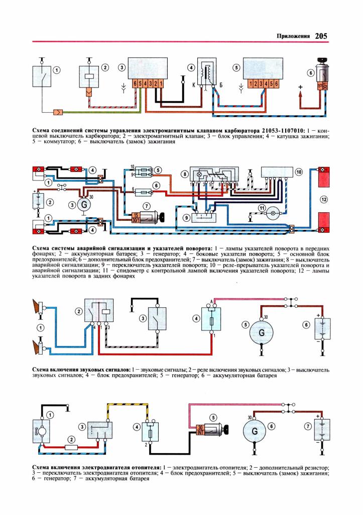
- (power - 16A) - responsible for the sound, signaling lights of the front doors, ceiling lamps, cigarette lighter, clock;
- (power - 8A) - controls the relay, heater, electric motor windshield, windscreen wipers;
- - controls the high-beam headlights on the left side and the control lamp;
- - manages the far headlights on the right;
- - responsible for the operation of the left dipped headlights;
- - controls the right low beam headlights;
- - is responsible for the left front and right rear dimensions, and for lighting the rooms;
- - monitors the operation of the right front and left rear dimensions, as well as the engine compartment lighting and control lamp;
- - Responsible for rear traffic lights, turn signals, luggage compartment lighting, oil pressure indicator, brake light, tachometer;
- - controls the voltage regulator;
- - backup fuses (RP);
- - RP;
- - RP;
- - supervises the operation of the electric heating of the rear window;
- - controls the operation of the fan and the cooling of the motor;
- - Responsible for the operation of emergency mode indicators.
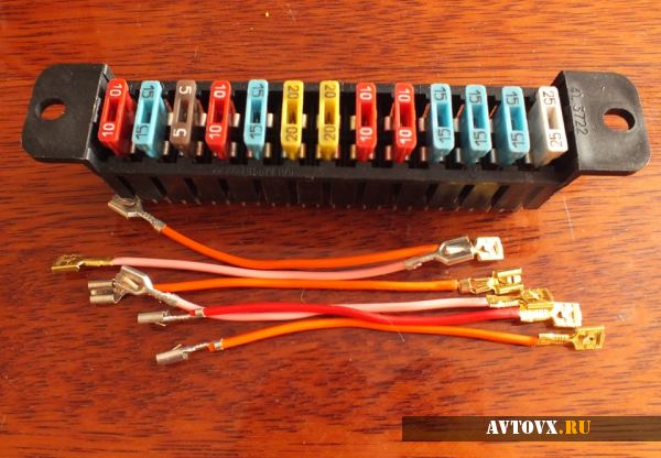
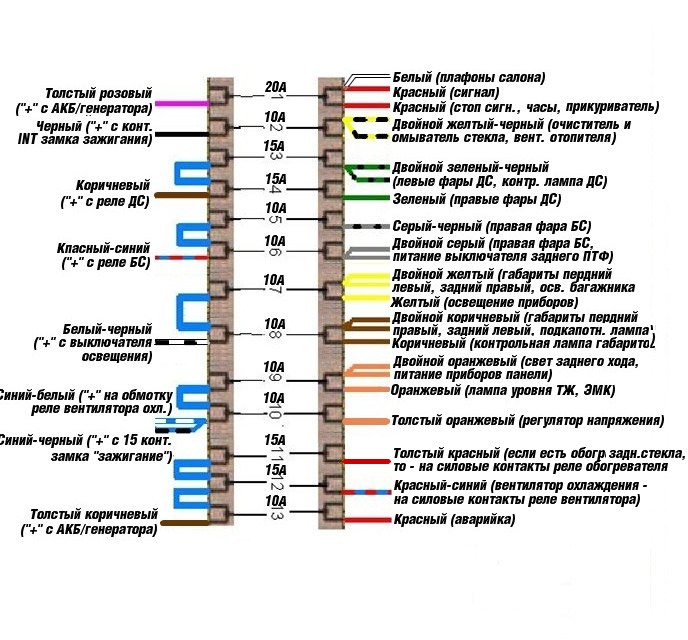
Flag fuses are installed on the euro fuse blocks on the VAZ-2106 (new-style boxes). The first of them has a power of 16 A, all the rest - 8A. The wiring diagram for the Euro fuse box VAZ 2106 is given below.
- - responsible for the sound signal, interior lighting, brake lights, clock and cigarette lighter;
- - windshield washer, heater motors, wiper relay;
- - high beam on the left and high beam indicator;
- - high beam on the right;
- - dipped beam on the left;
- - dipped beam on the right and rear fog lamp;
- - left front and right rear dimensions, luggage compartment lighting, lighting state number car, cigarette lighter lighting, instrument lighting;
- - right front and left rear dimensions, engine compartment lighting;
- - indicators of oil pressure, temperature of the liquid for cooling, fuel level, electric heating of the glass at the rear, turn signals;
- - regulates the voltage of the generator;
- - reserve (P);
- - electrically heated glass at the rear;
- - cooling system;
- - emergency mode.
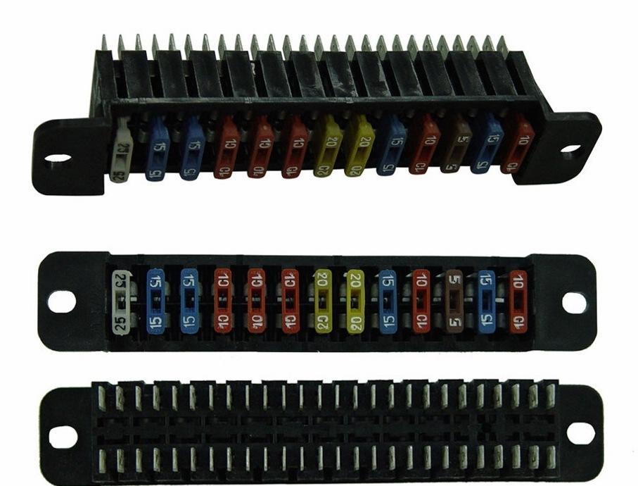
The scheme of a conventional fuse block VAZ 2106 and the scheme of a new model box are very similar. The difference is in the details themselves. In the usual "black box" knife fuses are used, and in the block of the new sample - flag ones.
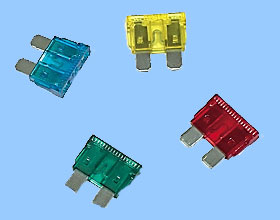
Types of fuses
A competent choice of fuses will save the owners of the VAZ-2106 from serious problems. Incorrectly selected parts can lead to problems such as a car fire. When choosing these parts, you should pay attention to the current strength in them, which is expressed in amperes. Fuses of different amperage have a corresponding digital marking, and also differ from each other in color. For example, brown ones have a rating of seven and a half amperes, blue ones - 16A, green ones - 20A. It is important that the ratings of each part match the manufacturer's recommendations.
Replacement
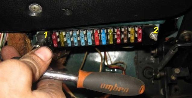
The fuse mounting block on the VAZ-2106 is located under the dashboard, on the left side of the driver. For aesthetics, it is covered with two covers that are held on by small latches. To gain access to the block, these caps are removed with a slight movement.
To replace, you will need a new blade fuse box and a wire with a cross section of approximately 2 mm 2. To replace the old "black box" with a new one, you will need to perform the following steps.
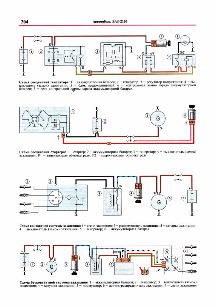
In a VAZ 2106 car, the fuse box (hereinafter referred to as the PSU) is one of the simplest in the VAZ line. There are no circuit boards or diodes in it, however, it is worth paying attention to the functioning of this device, since the operation of electrical appliances depends on it. We invite you to find out what electrical equipment the VAZ 2106 fuses are responsible for and how they are replaced.
Location and wiring diagram
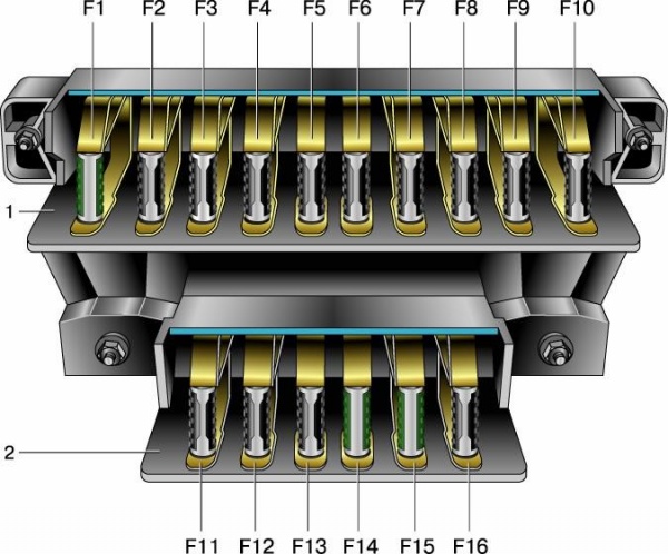
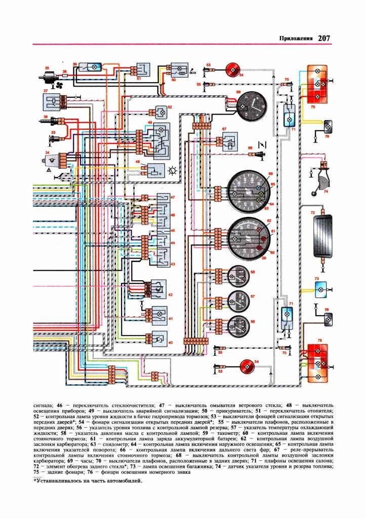
The PSU itself consists of two lines with fuses, which is installed in the passenger compartment of the car and is attached to the body with two nuts. In particular, it is located on the side driver's seat under the instrument panel. Below is a diagram of the device, as well as the purpose of each element.
As you can see, almost all domestic car circuits are protected by fusible devices. However, there are exceptions here too. In particular, we are talking O:
- solenoid starter relay - it is missing;
- the power supply circuit of the relay coil, which ensures the operation of the radiator fan of the cooling system, is also not protected;
- the ignition coil is also not protected by the relay;
- if an old-style power supply is installed on your car, then it does not have a switch power supply circuit and a Hall sensor.
The element installed in the PSU is designed for a certain voltage in the wiring. This voltage is calculated by a simple formula - the voltage of all energy consumers in the wire must be multiplied by the reserve number, which is from 1.2 to 1.5. So what's for that? in order for the operation to be stable, the denomination of the block elements must match.
It must be added that very often the owners of 2106 make mistakes by using an ordinary coin instead of a fusible device. It is better not to do this, because at any time you may have a short circuit in your car. Therefore, old-style power supplies, like any other machine component, also require periodic maintenance. Due to design features, that is, weak PSU holders or regularly oxidized tips, you may notice burning of the contact part.
Thus, due to the increased contact resistance, overheating occurs and the contact condition of the element deteriorates. As a result of this, additional problems with the wiring of the vehicle may appear. To prevent this from happening, you should periodically, at least twice a year, inspect the PSU as a whole. Clean the landing slots, inspect the PSU and change the failed fuses in time.
But this is all about the old-style PSU. Some owners of these car models, given the problems that periodically appear with the old-style PSU, change it to a new one.
Removal and replacement process
There is nothing difficult in the process of changing PSU parts, so we will not describe this process. But we will tell you how to change the old-style PSU to a new-style device.
- First of all, disconnect the battery. Now open the driver's door and use a screwdriver to pry off the two fasteners for attaching the decorative trim to the interior. Move it aside and you will see a block. Using a Phillips screwdriver, unscrew the PSU mounting screws. Do this carefully so that the wires do not fly off the terminals in the process.
- As soon as the PSU is unscrewed, take it down. But do not pull it hard, so as not to break the wires. Note! Jumpers must be installed on those wires through which voltage is supplied from the engine compartment. Do not connect a jumper after the fuse itself, otherwise, as a result, voltage will pass through one part, supplying several components of electrical equipment.
- The jumper setting order should be: 3-4, 5-6, 7-8, 9-10, 11-12, 12-13.
- Now you need to dismantle each wire in turn, starting with the first fuse from the old PSU, and mount it on the new one. Do this operation with each contact, up to the very last wire. When all the contacts are in place, you should check if you did everything right. In particular, you need to turn on the source of voltage consumption and pull out the appropriate fuse. If the device ceased to function, then all actions were performed correctly. For example, turn on the dipped headlights and pull out one of the PSU elements responsible for the left or right headlight. If it goes out, then you did everything right.
- Do the same for each fuse. If the device continues to work when the element is dismantled, then the jumper is most likely not installed correctly, so double-check the connection diagram.
This completes the replacement of the PSU with a new device. As you can see, this is not difficult, but if you are not sure that you will do everything right or cannot distinguish the blue wire from red or green, then entrust this matter to an electrician.
- From time to time, clean the landing slots. As you might guess, the functionality of PSU devices depends not only on their performance, but also on the cleanliness of the seat. The cleaner the socket, the less resistance in this section of the wiring, respectively, the heating of the element will also be optimal. If the contacts are dirty, then the PSU device can heat up and melt over time, which will lead to loss of contact.
- Be sure to keep track of what part you install in the block. A mismatch of ratings can provoke irreversible consequences. This is especially true if the fuse box is not cleared. If the manufacturer recommends that 10 amp parts be installed in the unit, then use only such components. If you decide not to follow these tips from the car manufacturer, then at least this can result in the breakdown of certain electrical appliances. Moreover, a short circuit is possible and, as a result, a fire.
The regular fuse box VAZ 2106 is a complex of devices for preventive protection of the vehicle's electrical circuits, combined into one command block.
Such a fuse box, the diagram of which is presented below, is located on the right side, below the instrument panel on the driver's side, near the engine compartment opening handle. The correct connection of the VAZ 2106 fuse box is carried out according to the connection sequence printed on the cover of the new fuse box, which is installed during replacement or repair.
The existing wiring diagram of the fuse box will help to correctly use the vehicle's power supply system, significantly improving its conductive properties.
Features of the operation of the "six" fuse box
The features of the operation of the "six" fuse box include the following rules:
- It is not recommended to replace defective products with devices with different current strength characteristics.
- It is strictly forbidden to install the so-called. "bugs" (self-made products) instead of the previous faulty parts, as well as jumpers and non-standard products.
- It is advisable to have in stock a new set of factory products with different current strength parameters.
You can buy a factory fuse box in a specialized car shop of the VAZ concern. And the elements in it have different nominal current values, which is expressed in the width of the metal strip connecting the end planes of the products. Broadband elements are used to protect high current circuits, and narrowband - circuits with low current strength.
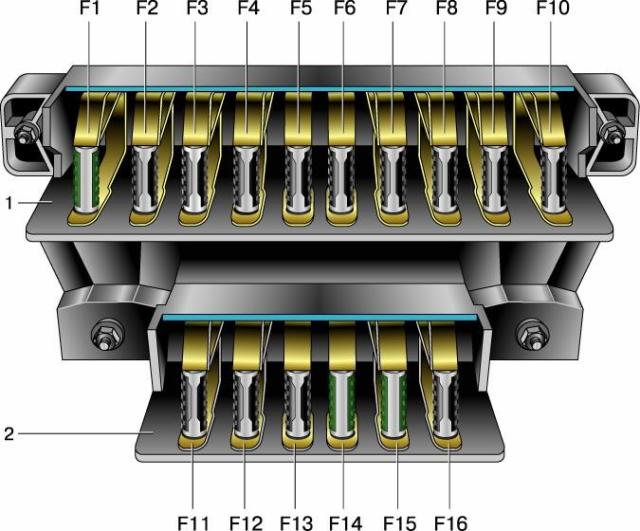
The fuse block is structurally composed of two adjacent blocks - the main one (with large dimensions) and the spare one (smaller).
Replacing fuses VAZ 2106
To replace the VAZ 2106 fuses with updated elements, the following steps are required:
- We remove the protective cover of the fuse box by drowning the latch, and do the following.
- We visually assess the condition of externally serviceable products, check their condition for burnt areas, if necessary, change them to serviceable parts, test the condition of the fasteners and bring them into working position.
- The fuses of the VAZ 2106 electrical circuit, drawn on the protective cover, will help in identifying the chain of defects in this element of the vehicle's power equipment.
These protection elements of the electrical circuits of the car are divided into the following types: fuses made of plastic and fuses made of ceramics. The first products are not heat-resistant, and the second ones are somewhat fragile. Although the reliability of both is undeniable, preference should be given to ceramic parts.
The euro standard fuse box is a restyled version of this element, and you can do it yourself. To install Euro-class fuses, you need to purchase a similar product from a GAZ 3110 car, however, the VAZ 2106 fuse circuit does not correspond to the rating of those devices that are used in the Volgovskaya model. They need to be replaced. In addition, you will need 2 mm thick wire for making jumpers, 6 mm heat shrink material and the required number of special type connectors.
The following actions:
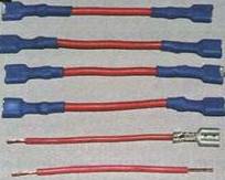
- We make jumpers (we cut pieces of wiring, install connectors and crimp their end fasteners).
- We find the euro fuse scheme for the VAZ 2106.
- We insert jumpers according to the found scheme.
- We turn to work on the vehicle and start by removing the battery terminals, thereby depriving the car's power system of power.
- We dismantle the old one and fix the new fuse box, while removing the old mounts that have become unnecessary in the form of the Latin "z".
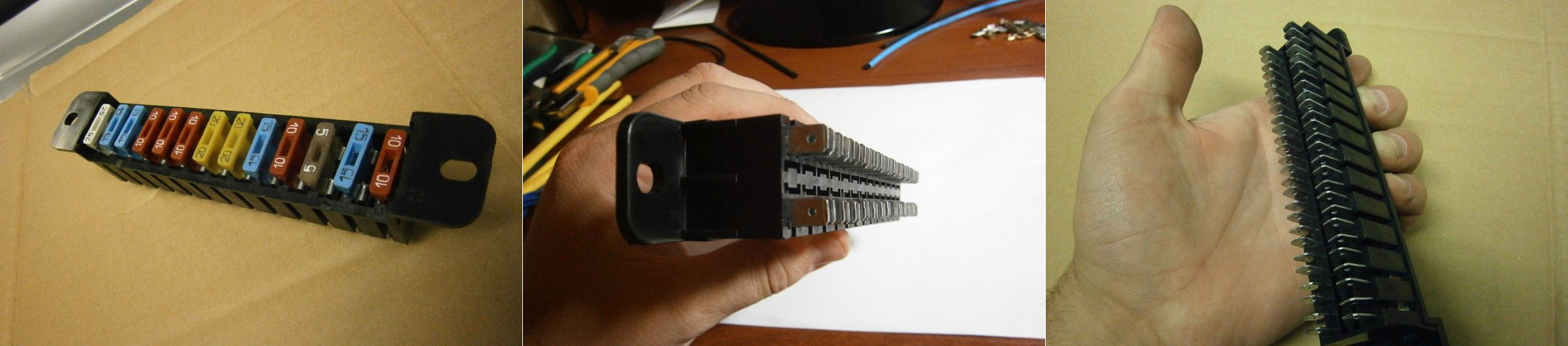
- We determine the input and output channels of the block device, and it is quite easy to distinguish: single-plug contacts are input, two-plug contacts are output.
- An important addition: due to the close dislocation of the contacts of the incoming and outgoing type, they must be insulated with heat-shrinkable material.
At the end of the installation, the product should be adapted to the new lodgement, because it takes up much less space than the previously installed energy supply element of the Six. Here is such a diagram of the VAZ 210 euro fuses, converted from the GAZ model fuse box, is used in modern version"sixes".
The difficulty lies in the fact that it is almost impossible to get the required ratings of 8 and 16 A, therefore we will adapt to the nearest parameters - 7.5 A (brown) and 15 A (blue). Therefore, the VAZ 2106 fuse connection diagram in the updated version will be adapted for fuses of current values \u200b\u200bclose in nominal value. It is this scheme that will work much better than previous samples.
Almost all electrical equipment of the car is powered by fuses installed in a special block (often located on the left side under the instrument panel). Such foresight is not "born" out of the blue. When a short circuit occurs in the on-board network, the fusible insert of the corresponding fuse burns out and that's it. If there were no such protection, then the car’s battery would simply fail, and then it would have to be changed already.
Design features
The convenience and ease of replacing a burnt-out fusible link largely depends on the structure and location of the safety block. And if in modern cars this moment is well thought out, then in old VAZ cars the design of the block is very inconvenient, and the process of removing and installing the fuse requires a lot of effort from the motorist. In such a situation, the only way out is to remove the old block and put a euro fuse box in its place. But how to do it right?
Replacing the fuse box on the VAZ-2106
As practice shows, replacing a standard block with a euro option is a very useful alteration. At the same time, there are no special difficulties in the work. Proceed in the following sequence:
- Buy a new safety block from a GAZ-3110 car. It can be purchased at any automotive store (there will be no special problems here). The average price is from 300 rubles. By the way, all the necessary fuses are included in the kit. The only negative is that the value of not all fuses matches. So you have to spend a little, but these are trifles.
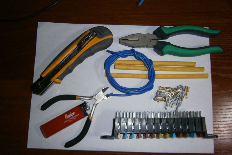
- Prepare necessary material(what is not - buy). You will need heat shrink with a diameter of 6 mm, connectors, as well as wires with a cross section of 2-2.5 mm2.
- Prepare the necessary jumpers in advance (you can do this at home, sitting at the table). To do this, take the purchased wire and cut out six equal pieces of 10-12 centimeters each. If the car is not equipped with rear window heating, then you can get by with five jumpers, because the last contact Group not involved.
- Using a special tool, install the connector on the stripped edge of the flexible copper wire (by crimping) and put on heat shrink. In this case, the insulation of the conductor is almost perfect. You should get six (five) jumpers with connectors on the edges.
- Take the safety block diagram for your car (it is very difficult to navigate without it). With the diagram in hand, you will see which fuses are needed and where to install them.
- Please note that after installing a new block for spare fuses, there will be no room left.
- Mount the previously prepared jumpers on the safety block. When all six jumpers are installed, the homework can be considered completed.
- Go directly to the car, open the hood and remove the "minus" and "plus" from the battery.
- Dismantle the old unit and remove the Z-type fixing clips.
- Turn the block in your direction so that you can understand what, from where and where it is connected. Find the entry point to the fuse block and the exit points after the fuses. It's not hard to navigate here. If there is only one contact in each of the terminals, then this row is the input. A row where two wires are connected to the terminals is the output. Typically, the top row is the input and the bottom row is the output.
- Holding both blocks in the air, gradually rearrange the wires from the new to the old node. At the same time, act in strict sequence so as not to get confused. Please note that in the new block, the entrance and exit will be double. To avoid a short circuit, it will not be superfluous to pre-isolate each contact with heat shrink. Such foresight can be very helpful in the future.
- After installing each wire, check the quality of the work done by the usual pulling.
- Once all the wires are installed, inspect the block again. You should not have unused terminals left.
- Now attach the new fuse box to its original location. But how to implement this, because the block sizes are different? - Yes, it's very simple. Those "ears" that remained from the old device are quite suitable for mounting a new design. But something still needs to be fixed. In particular, it is desirable to slightly bend one of the “uhs” towards its “brother”, that is, to make the distance between them a little smaller. For this, no additional tools are needed - just the effort of the hand.
- Install the new fuse box in place (now it should fit snugly and efficiently into the new design). It remains to tighten it with nuts and "voila" - the work is completed.
- If desired, you can “drown” the block a little inside the instrument panel. This adds some aesthetic to your rework and will keep the block out of sight.
Denominations
As we have already mentioned, the fuse ratings of the GAZ block are slightly different from the VAZ-2106. Hence, small adjustments are inevitable. In the new block, fusible inserts are mainly installed with ratings from 5 to 25 Amperes. You also need other denominations - 8 and 16 Amperes.
And here you will most likely encounter another problem - you may not come across such denominations for the euro fuse box. But you can find a way out by selecting the fuses closest in terms of performance, for example, 7.5 Amperes and 15 Amperes (it is better to take a slightly lower current rating).
It will not be superfluous to get special tweezers for replacing fuses. The thing is “penny”, and the work of replacing it makes it much easier. If you get fuses with platypuses, then you can accidentally break everything.
After replacing the fuses, return the battery terminals to their place and check the operation of all electrical appliances.
Conclusion
That's it - you're done great job to replace the outdated fuse box in the VAZ-2106 with a newer and more modern one. You can safely be proud of yourself and use the alteration to your pleasure. Good luck.
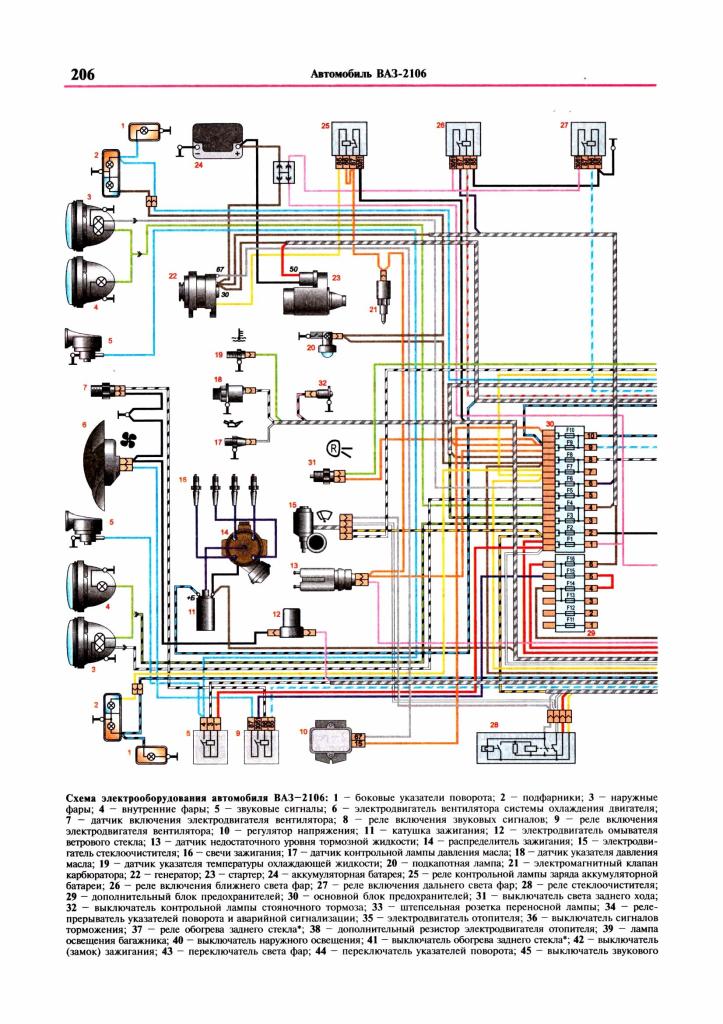
Blocks of fuses for electrical circuits (main and additional) are installed in the passenger compartment to the left of the steering column under the instrument panel. The fuse numbers are printed on the block covers. Depending on the strength of the maximum current, the fuses have different colors.
Considered cars VAZ 2106 with engines 21011, 2103, 2106
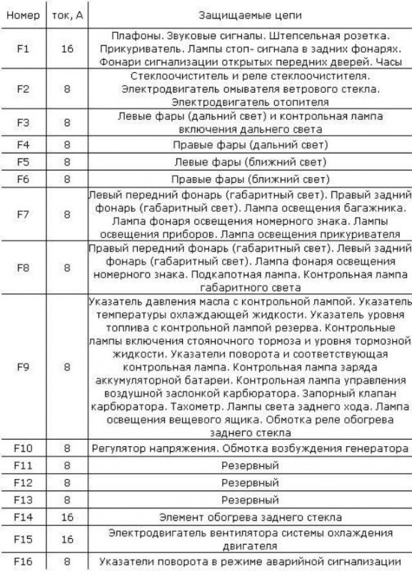
Fuse decoding
| Number | current, A | Protected circuits |
| F1 | 16 | Plafonds. Sound signals. Plug socket. Cigarette lighter. Stop lamps in rear lights. Lights signaling open front doors. Watch |
| F2 | 8 | Wiper and wiper relay. Windshield washer motor. Heater motor |
| F3 | 8 | Left headlights (high beam) and high beam warning lamp |
| F4 | 8 | Right headlights (high beam) |
| F5 | 8 | Left headlights (low beam) |
| F6 | 8 | Right headlights (low beam) |
| F7 | 8 | Left front lamp (side light). Right rear lamp (side light). Trunk light. License plate lamp. Instrument lighting lamps. Cigarette lighter lamp |
| F8 | 8 | Right front lamp (side light). Left rear lamp (side light). License plate lamp. Hood lamp. Side light warning lamp |
| F9 | 8 | Oil pressure indicator with control lamp. Coolant temperature gauge. Fuel gauge with reserve warning lamp. Control lamps of inclusion of a parking brake and level of a brake liquid. Direction indicators and corresponding control lamp. charge control lamp battery. The control lamp for controlling the air damper of the carburetor. Shut-off valve for carburetor. Tachometer. Reversing lamps. lighting lamp glove box. Heated rear window relay coil |
| F10 | 8 | Voltage regulator. Generator excitation winding |
| F11 | 8 | Spare |
| F12 | 8 | Spare |
| F13 | 8 | Spare |
| F14 | 16 | Rear window heating element |
| F15 | 16 | Engine cooling fan motor |
| F16 | 8 | Direction indicators in alarm mode |
Relay replacement
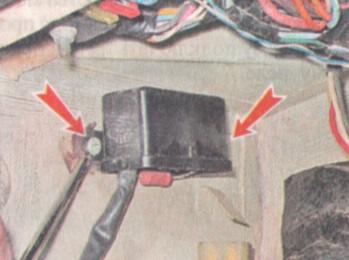
Wiper Relay Replacement (PC514)
The wiper relay is located in the passenger compartment on the left side of the body under the instrument panel and is designed to provide intermittent operation.
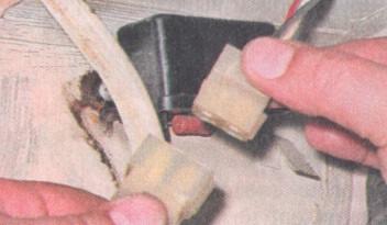
You will need two plastic upholstery holders to complete the job.
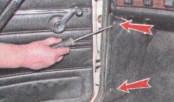
1. Having removed the seal from the flanging of the front pillar of the driver's door, pry off the sidewall upholstery with a screwdriver and remove it, removing the two holders from the holes in the sidewall (the holders are usually destroyed in this case). We bend the soundproofing.
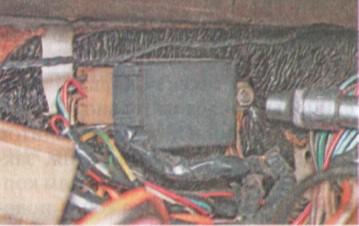
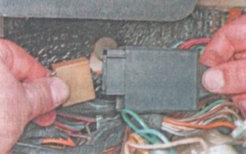
2. Disconnect the relay wire block from the harness. The connector is located at the bottom of the instrument panel
Using a Phillips screwdriver, unscrew the two screws and remove the relay
Installation is carried out in the reverse order. We fasten the upholstery of the sidewall with new holders.
Replacing the relay-interrupter of the direction indicator and alarm (231.3747 or 23.3747)
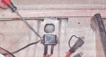
The relay-breaker is installed on the bulkhead of the engine compartment behind the instrument panel. The relay is designed to receive an intermittent light signal of the direction indicators both in the alarm mode and in the direction indication mode and to monitor the health of the direction indicator lamps. When the lamp burns out, the relay doubles the flashing frequency.
1. Remove the instrument panel (see p. 174, "Instrument panel - removal and installation").
2. Using a 10 mm socket wrench, unscrew the relay mounting nut. Under the nut are the tips of the two "mass" wires.
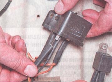
Disconnect the wiring harness from the relay
Installation of all removed parts is carried out in the reverse order.
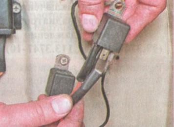
Replacing the headlight switch relay (90.3747-10 or 113.3747-10)
Two relays for switching on the low and high beams are installed in the engine compartment on the top of the right mudguard.
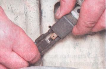
Using a Phillips screwdriver, we unscrew the fastening screw and remove the relay. Under the bracket for fastening the high beam relay, there is a tip of the mass “wire”.
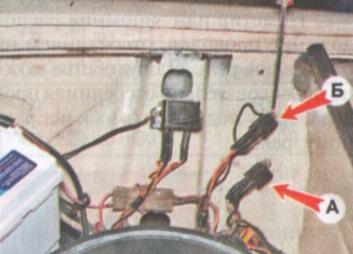
A - relay for switching on the high beam,B- Low beam relay.
Having marked or remembered the location of the wires, we disconnect them from the relay outputs. For convenience, you can sequentially disconnect the wires and immediately connect them to a working relay.
 Installation of all removed parts is carried out in the reverse order.
Replacing the Battery Warning Lamp Relay (PC702)
The relay is located in the engine compartment on top of the right mudguard. The relay is used to turn on the warning lamp on the instrument panel in the event of a malfunction in the battery charging circuit. When the ignition is on, the control lamp is on, and after starting the engine (with a good charge circuit), the lamp should go out
1. Using a Phillips screwdriver, we unscrew the two fastening screws and remove the relay. A "mass" wire is fixed under one of the screws.
2. Having marked or remembered the location of the wires, disconnect them from the relay outputs. For convenience, you can sequentially disconnect the wires and immediately connect them to a working relay.
The relay is installed in the reverse order.
Replacing the relay for turning on the radiator fan of the cooling system (90.3747-10 or 113.3747-10)
The relay for turning on the radiator fan of the cooling system is installed in the engine compartment on the top of the left mudguard.
1. Using a Phillips screwdriver, unscrew the fastening screw and remove the relay. 
2. Having marked or remembered the location of the wires, disconnect them from the relay outputs. For convenience, you can sequentially disconnect the wires and immediately connect them to a working relay.
Wiring diagrams (fuses and relays) of electrical equipment VAZ 2106
Click on the image to enlarge
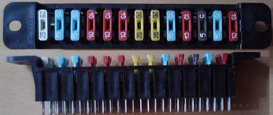
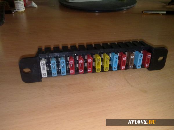
New VAZ 2106 fuse box or Euro 2106 fuse box
Installation. How to properly connect the block.
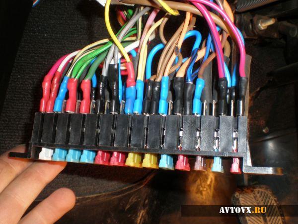
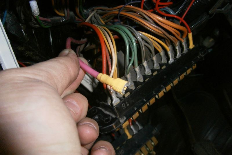
First you need to disconnect the ground from the battery. Then we unscrew the old fuse block, carefully so that the wires with the terminal do not fly off.
After you have unscrewed the block, you need to take it down as far as the wires allow.
Installation diagram.
Important!!! You need to install jumpers on those wires that come with voltage from the engine compartment, that is, from the wire of the voltage source, install up to the fuse. If you connect a jumper after the fuse, it turns out that current passes through one fuse, which feeds two consumers.
Jumper Setting Order
3-4, 5-6, 7-8, 9-10, 11-12, 12-13
Next, we remove one wire at a time (starting with 1 fuse) from the old block and rearrange it to a new one, and so on until the last block. After installing all the wires, you need to check the correct connection, this is quite easy to do. For example, turn on the dipped beam and pull out fuse No. 5, respectively, the left headlight should go out, insert the fuse into place, pull out fuse No. 6, the right headlight should go out. If this happens, then these circuits are connected correctly. By analogy, it is necessary to test the remaining circuits.
If, when pulling out one fuse, two headlights are still on (for example, or the equipment is working), then the jumper is not installed correctly, check the connection diagram.
this is how it looks