Fitting under the thrust bearing on the shaft. Tolerances and fits of rolling bearings
Single-row deep groove ball bearings, in their design, are capable of absorbing, along with a radial load, small axial loads acting in both directions along the shaft axis.
Single row deep groove ball bearings are capable of operating at higher speeds than bearings of other design varieties, but of the corresponding dimensions. The maximum permissible speed of single-row radial ball bearings can be increased by using special lubrication regimes, installing bearings of a high accuracy class, as well as using bearings with cages made of antifriction materials (textolite, brass, bronze, duralumin).
Single row deep groove ball bearings have the lowest friction losses compared to other types of bearings with corresponding dimensions.
For good performance of ball bearings in mechanisms, an optimal radial clearance is required. The initial radial clearance of a rolling bearing is the free space between the rolling elements and the rings in the diametral direction, which the bearing has in the unmounted state.
The initial radial clearance after mounting can change significantly under the influence of the fit interference, the shape of the seats, changes in the temperature of the bearing rings and parts of the bearing unit during operation, load, misalignment of the seats and a number of other reasons.
Initial radial clearances of ball bearings.
Main row.
Bearing inner diameter:
d to 10mm - gap from 0.005 to 0.016 mm.
d over 10 to 18 mm - clearance from 0.008 to 0.022 mm.
d over 18 to 30 mm - gap from 0.010 to 0.024 mm.
Bearings with reduced and increased initial radial clearance are also available.
Bearing accuracy classes.
Bearing accuracy classes are characterized by the values of maximum deviations of dimensions, shape, and relative position of bearing surfaces.
For ball bearings, the following classes are established in order of increasing accuracy: 8, 7, normal, 6, 5, 4, T, 2. according to GOST520-2002.
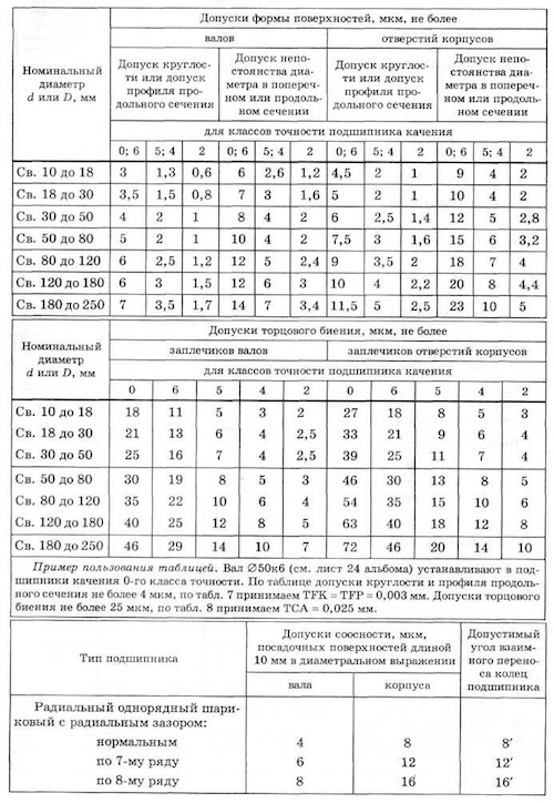
Permissible deviations for the landing dimensions of bearings according to GOST520-2002.
Sketch 203 of the bearing with tolerances for dimensions and tolerances for the shape and location of surfaces.
Bearing fittings.
Bearing fits are selected depending on the operating mode, type of loading and accuracy class.
Operating modes - heavy, normal, easy.
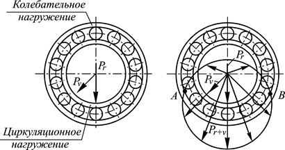
Types of loading - circulation, local, oscillatory.
Crankshaft bearings: Operating mode - heavy.
Types of loading:
The outer ring of the bearing is local.
Internal - circulation.
Preparation for installation of seats.
Roughness and deviations from geometric shape mounting surfaces of shafts and housing openings, as well as tolerances are carried out in accordance with the requirements of GOST 3325-85.
Sketch of seats for 203 bearing of normal accuracy in accordance with GOST 3325-85.
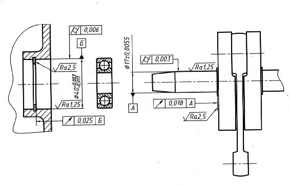
Let's see a sketch of the seats.
Hole manufacturing tolerance = 0.016mm.
Hole cylindricity tolerance = 0.006mm.
Shaft manufacturing tolerance = 0.011mm.
Shaft cylindricity tolerance = 0.003mm.
Rhetorical question: Is it possible to restore worn bearing seats without subsequent machining by punching, soldering, welding, applying various foils, etc.?
Parts of mechanisms intended for mounting bearings, with the presence of nicks on the mounting surfaces, corrosive deposits, with deviations from the correct geometric shape, should not be allowed for mounting.
Lubricate suitable shaft and housing seats before installation.
Handling of rolling bearings.
Do not prematurely remove the bearing from the packaging. Only immediately before installation, the bearing must be unpacked and washed in gasoline or hot water. mineral oil. Dry bearings should not be rotated. To protect the bearing from corrosion, do not handle it with unprotected hands. To do this, use gloves or a clean cloth. Lubricate bearings before mounting.
Mounting of bearings.
In all cases of mounting rolling bearings, it is necessary to avoid the transmission of forces during pressing through the rolling elements. The bearing must be mounted on the shaft through the inner ring and into the housing through the outer ring.
Incorrect and careless installation is one of the main causes of premature failure during operation.
Literature:
1. Ball and roller bearings. Catalog - reference book. Moscow 1963
2. GOST520-2002.
3. GOST 3325-85.
Local loading of the ring - loading under which the working on bearing, the resulting radial load is always taken up by the same limited section of the raceway of this ring (within the boundaries of the load zone) and transferred to the corresponding section of the seating surface shaft or torso.
The ring can be stationary with respect to the current on its load or ring and load take part in the total rotation.
On rice.
34 shows the events of local loading of the rings (a - external, b - spiritual) with the corresponding diagrams of normal stresses on landing surfaces.
Standard Pairing bearing with mating parts is formed like a combination of tolerance fields for connecting dimensions of bearing rings with standard tolerance fields shafts and holes.
In this regard, it is possible to achieve increased accuracy landings by redistributing the accuracy of mating parts, into details, tightening tolerances on connecting dimensions of rings bearings.
With this type, there is a need to form special standards for bearing seats rolling, which actually regulate the tolerance fields for the dimensions of parts mating with bearings, as well as other requirements for the accuracy of their geometric parameters.
Landings groups H / d (H 8/ d 9, H 9/ d 9 ě°˝€ ” preferred and similar landings, formed from tolerance fields of qualifications 7, 10 and 11) are used relatively infrequently.
For example, landing H 7/ d 8 is used at high speed and relatively low pressure in large bearings, as well as in the “piston-cylinder” interface in compressors, and landing H 9 / d 9 - with low accuracy of mechanisms.
Real porn is the solution to this problem: 1.
Take a core.
Place bearing fit very often to pierce, the frequency of puncturing depends on how long this hemorrhoid passes.
This type of my dad often planted bearings on own Jupiter's knee.
Threat nothing will help if you have a backlash m / y of the inner clip bearing and shaft .
If you were closer, I would shaft used shvbsk
Some bearings installed without seals on the shaft with lubricant drunk during their manufacture.
Before installing these bearings are not subject to redemption.
Bearings without seals and lubrication before installation on the shaft subject to depreservation and washing.
Before assembly, they are unpacked and thoroughly washed in a 6% solution of oil with gasoline or in a hot anti-corrosion aqueous solution, and then visual inspection is carried out.
At the same time, they are convinced of the absence of corrosion, burns, cracks and other mechanical damage.
They check the marking, ease of rotation, noise and, if necessary, dimensions, radial and axial runout, radial clearance, initial axial play.
Control methods and technical requirements are given in GOST 520 - 71.
Landings rings that are stationary with respect to the load are assigned more freely, allowing for a small gap, since in this case the rings do not run in the mating parts.
Irregular rotation of a non-rotating ring of the order of one turn per day is useful, since this changes the position of its load zone, which helps to increase durability bearing.
In addition, the interface facilitates the axial movement of the rings during installation, when adjusting the gaps in bearings and at temperature deformations.
This entry indicates that the mating is done for a cylindrical mating with a nominal diameter of 80 mm in the system shaft, since the tolerance field shaft denoted by h6 (the main deviation for h is zero and corresponds to the designation of the main shaft, and the number 6 shows that the tolerance for the shaft must be taken according to the sixth grade for the size range (over 50 to 80 mm, to which the size 80 mm belongs);
hole tolerance field F7 (basic deviation F with grade tolerance 7).
When choosing landings with an interference fit (part of transitional and press landings) it is necessary to include that the gap in bearing can decrease from 50 to 80% of the measured tightness depending on the stiffness of the rings bearing and material of mating parts from?
for stretching the inner rings and compressing the outer ones.
This is especially true for small, non-rigid ball bearings having negligible radial clearance.
So, in such events it is good to take landings with little or no tension.
The standard also normalizes the end runout of the shoulders shafts and holes in the hulls and deviations from the alignment of the landing surfaces bearings about their common axis.
Alignment tolerances can be replaced by tolerances for radial runout of the same surfaces about their common axis, taking into account the fact that on the same surfaces are necessarily given cylindricity tolerances, which, together with the radial runout tolerances, limit similar deviations that limit the alignment tolerances.
Choosing the right fit, ensuring the required cleanliness and dimensional tolerances of bearing surfaces is a key factor in ensuring the durability, reliability of mechanisms.
Proper fit is essential for bearing performance.
Based on the characteristics of the bearing, the ring that rotates must be fixed on the supporting surface motionless, with an interference fit, and the fixed ring should fit into the hole with a minimum clearance, relatively freely.
An interference fit of the rotating ring prevents it from turning, which could lead to wear of the bearing surface, contact corrosion, unbalance of the bearings, flaring of the support, excessive heating. So, basically, the bearing is mounted on a shaft that operates under load.
For a fixed ring, a small gap is even useful, and the possibility of turning no more than once a day makes the wear of the supporting surface more uniform and minimizes it.
Basic terms
Let us consider in more detail the basic terms and concepts that determine the fit of bearings. Modern mechanical engineering is based on the principle of interchangeability. Any part made according to one drawing must be installed in the mechanism, perform its functions, and be interchangeable.
To do this, the drawing determines not only the dimensions, but also the maximum, minimum deviations from them, that is, tolerances. Tolerance values are standardized by a single system for tolerances, ESDP landings, broken down by degrees of accuracy (qualities), are given in tables.

They can also be found in the first volume of Anuryev's Handbook of Mechanical Engineer, and GOST 25346-89, as well as 25347-82 or 25348-82.
Characteristics
- Author: Vasily Anuriev,
- Number of pages: 2696
- Year of issue: 2015
- publishing house: Engineering,
- Binding: Hard cover
- Publication language: Russian
- Publication type: Separate edition
- Packed weight, g: 3960
Handbook of the designer-machine builder. Volume 1The first volume contains general technical information, reference data on materials, surface roughness, tolerances and fits, maximum deviations in the shape and location of surfaces, structural elements of parts, fasteners, ...
According to GOST 25346-89, 20 accuracy qualifications are defined, but in mechanical engineering they are usually used from 6 to 16. Moreover, the lower the qualification number, the higher the accuracy. For landings of ball and roller bearings, 6.7, less often 8 qualifications are relevant.
Within the same qualification, the size of the tolerance is the same. But the upper and lower deviations of the size from the nominal are located in different ways and their combinations on the shafts and holes form different landings.
There are landings that provide a guarantee of clearance, interference and transitional, realizing both the minimum clearance and the minimum interference. Landings are indicated in Latin lowercase letters for shafts, large for holes and a number indicating quality, that is, the degree of accuracy. Landing designations:
- with clearance a, b, c, d, e, f, g, h;
- transitional js, k, m, n;
- with interference p, r, s, t, u, x, z.
According to the hole system for all qualifications, it has a tolerance of H, and the nature of the fit is determined by the shaft tolerance. This solution allows you to reduce the number of required control gauges, cutting tools and is a priority. But in individual cases a shaft system is used in which the shafts have an h tolerance and the fit is achieved by machining the hole. And just such a case is the rotation of the outer ring of a ball bearing. An example of such a design can serve as rollers or tension drums for belt conveyors.
Selecting a fit for rolling bearings
Among the main parameters that determine the fit of bearings:
- the nature, direction, magnitude of the load acting on the bearing;
- bearing accuracy;
- rotational speed;
- rotation or immobility of the corresponding ring.
The key condition that determines the landing is the immobility or rotation of the ring. For the stationary ring, a close clearance fit is selected and gradual slow turning is considered a positive factor that reduces overall wear, preventing local wear. The rotating ring must be planted with a reliable tightness, excluding rotation in relation to the seating surface.
Next an important factor which the bearing fit on the shaft or in the bore must correspond to is the type of loading. There are three key type loading:
- circulating during rotation of the ring relative to a radial load constantly acting in one direction;
- local for a fixed ring with respect to radial loading;
- oscillatory with a radial load oscillating relative to the position of the ring.

According to the degree of accuracy of the bearings in the order of their increase, they correspond to five classes 0,6,5,4,2. For mechanical engineering with loads of low and medium magnitude, for example for gearboxes, class 0 is common, which is not indicated in the designation of the bearings. For higher accuracy requirements, the sixth grade is used. At higher speeds 5.4 and only in exceptional cases the second. Sixth Grade Example 6-205.

In the process of actual design of machines, the fit of the bearing on the shaft and in the housing is selected in accordance with the operating conditions according to special tables. They are given in volume two of the Handbook of the designer-machine builder Vasily Ivanovich Anuriev.

For the local load type, the table suggests the following fits.
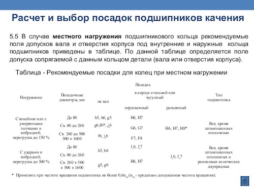
Under conditions of circulation loading, when the radial force acts on the entire raceway, the loading intensity is taken into account:
Pr=(k1xk2xk3xFr)/B, Where:
k1 – dynamic overload factor;
k2 is the attenuation coefficient for a hollow shaft or a thin-walled housing;
k3 is the coefficient determined by the effect of axial forces;
Fr - radial force.
The value of the coefficient k1 at overloads less than one and a half times, small vibrations and shocks is taken equal to 1, and with a possible overload from one and a half to three times, strong vibrations, strokes k1=1.8.
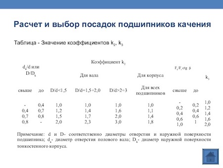
The values of k2 and k3 are selected according to the table. Moreover, for k3, the ratio of the axial load to the radial load, expressed by the parameter Fc/Fr x ctgβ, is taken into account.
The bearing fits corresponding to the coefficients and the loading intensity parameter are given in the table.
Processing of seats and designation of landings for bearings in the drawings.
The seat for the bearing on the shaft and in the housing must have lead-in chamfers. The roughness of the seat is:
- for a shaft neck with a diameter of up to 80 mm for a class 0 bearing Ra=1.25, and for a diameter of 80…500 mm Ra=2.5;
- for a shaft neck with a diameter of up to 80 mm for a bearing of class 6.5 Ra=0.63 and for a diameter of 80…500 mm Ra=1.25;
- for a hole in the housing with a diameter of up to 80 mm for a class 0 bearing Ra = 1.25, and with a diameter of 80 ... 500 mm Ra = 2.5;
- for a hole in the housing with a diameter of up to 80 mm for a bearing of class 6,5,4 Ra = 0.63, and with a diameter of 80 ... 500 mm Ra = 1.25.
The drawing also indicates the deviation of the shape of the bearing seat, the end runout of the shoulders for their stop.
An example of a drawing showing the fit of the bearing on the shaft Ф 50 k6 and the shape deviations.
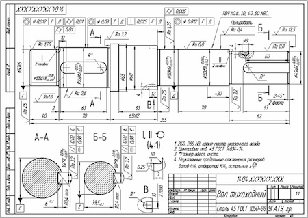
The values of form deviations are taken according to the table, depending on the diameter that the bearing has on the shaft or in the housing, the accuracy of the bearing.
The drawings indicate the diameter of the shaft and housing for fit, for example, F20k6, F52N7. On assembly drawings, you can simply indicate the size with a tolerance in the letter designation, but on the detail drawings, it is desirable, in addition to the letter designation of the tolerance, to give its numerical expression for the convenience of workers. The dimensions on the drawings are indicated in millimeters, and the tolerance value is in micrometers.
Selection of fittings for rolling bearings on shafts and housings
The reliability of bearing assemblies largely depends on right choice landings of bearing rings on the shaft and in the housing.
When choosing a fit, the following are taken into account: type of bearing; rotation frequency; load on the bearing (constant or variable in value and direction, calm or impact); rigidity of the shaft and housing; the nature of the temperature deformations of the system (increase or decrease in interference at operating temperatures); method of fastening the bearing (with or without tightening); ease of installation and dismantling.
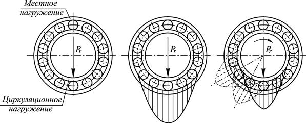
There are three main types of loading of rings: the ring rotates relative to the radial load, being subjected to the so-called circulation loading; the ring is motionless relative to the radial load and is subjected to local loading; the ring is loaded with a resultant radial load, which does not make a full turn, but oscillates by certain area ring, subjecting it to vibrational loading.
On fig. 5.27 shows the main types of loading of bearing rings, and in table. 5.12 - loading characteristics.
Rice. 5.27.
The landing is chosen so that the rotating bearing ring is mounted with an interference fit, which excludes the possibility of its slipping along the seating surface during operation under load; the other ring must be mounted with a gap. In this regard:
1) with a rotating shaft, it is necessary to have a fixed connection of the inner ring with the shaft; connect the outer ring to the body with a small gap;
2) with a stationary shaft, the inner ring must have a fit on the shaft with the required clearance, and the outer ring must be fixed in the housing.
In rolling bearings, a distinction is made between the initial, mounting and working clearance. The bearing has its initial clearance in the free state. According to GOST 24810-81, according to the types of bearings, symbols for clearance groups are established (designated in Arabic numerals)

and one of them with the word "normal"). The groups differ in the size of the radial and axial clearances. Mounting clearance is obtained in the bearing after its assembly in the product. Due to the fit of one ring with a guaranteed tightness, the mounting gap is always less than the original one. The most important in a bearing is the operating clearance - the clearance between the rolling elements and the raceways at steady state operating conditions and temperature. With a significant working gap, a large radial runout occurs, and the load is perceived by a smaller number of balls; with a working gap close to zero, the load is distributed on largest number balls, so the bearing in this case has a greater durability.
The mounting of the bearing with an interference fit is carried out mainly along the ring that experiences circulation loading.


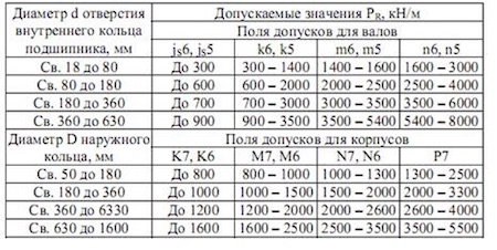
With circulation loading of the bearing rings, the landings are selected according to the intensity of the radial load Рн on the seating surface. Permissible values of Rn, calculated from the average values of the landing interference, are given in table. 5.14.
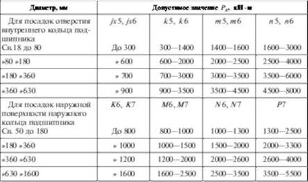
The intensity of the load is calculated by the formula
![]()
where Rg - radial load on the support; AG "K2, Kg - coefficients; b - working width of the seat (A \u003d B - 2r, where B is the bearing width; r is the coordinate of the mounting chamfer of the inner or outer ring of the bearing).
The dynamic landing coefficient K( depends on the nature of the load: with an overload of up to 150%, moderate shocks and vibration K( = 1; with an overload of up to 300%, strong shocks and vibration of the AG, = 1.8. The coefficient K2 (Table 5.15) takes into account the degree of relaxation of the fitting interference with a hollow shaft or a thin-walled housing, with a solid shaft K2 = 1. The coefficient Kg takes into account the uneven distribution of the radial load Fr between rows of rollers in double-row tapered roller bearings or between double ball bearings in the presence of an axial load Ftl on the support.
![]()
The values of Kg (Table 5.16) depend on the value For radial and angular contact bearings with one outer or inner ring Kr = I.
With an increase in the radial load, its intensity /> n (5.71) increases, and, consequently, the interference in the landings increases.
In landings of bearings of classes 0 and 6, tolerance fields of the 7th grade are used for the holes of the housings and the 6th grade - for the shafts. Landings of bearings of classes 5 and 4 are carried out more accurately than classes 0 and 6, by one quality.
Select the fit of the circulation-loaded inner ring of a single-row radial bearing 0-308 (accuracy class 0; d ~ 40 mm; O - 23 - 2-2.5 - 18 mm) on a rotating hollow shaft<іх ~ 20 мм. Радиальная реакция опоры Ря - 4119 Н. Нагрузка ударная, перегрузка 300%, осевой нагрузки на опору нет.
Solution. 1. We find the coefficients: A", \u003d 1.8; \u003d 1.6 (since --- \u003d 0.5; - \u003d 2.25); K5 \u003d 1 (since P0 \u003d 0).
2. We find the intensity of the load according to the formula (5.71):
In table. 5.14, the specified conditions for the shaft correspond to the tolerance field kv (since the accuracy class of the bearing is 0), which forms an interference fit with the tolerance field of the ring (A / ga | n \u003d 2 μm, A / ra4, ~ ~ 30 μm). Bearing diameter deviation e is accepted according to GOST 520-89 (upper 0, lower - 12 microns), and the shaft deviation - according to GOST 25347-82, respectively (ed - +18 microns, e ~ +2 microns).
The fit can also be determined by the minimum interference between the circulation-loaded ring and the surface of the part mating with it. Approximate minimum tension
![]()
where is the radial load; N - coefficient (for light series bearings it is 2.8, medium - 2.3 and heavy - 2).
According to the found value of A^n, the nearest landing is chosen.
The greatest interference fit should not exceed the allowable (L^< Л^оп) во избежание разрыва колец подшипника:
![]()
where [st] is the allowable tensile stress (for bearing steel [st] = 400 MPa).
Tolerances and fits of rolling bearings
To reduce the range, bearings are manufactured with deviations in the dimensions of the outer and inner diameters, regardless of the fit on which they will be mounted. For all accuracy classes of bearings, the upper deviation of the connecting diameters is assumed to be zero. Thus, the diameters of the outer and inner rings are taken respectively as the diameters of the main shaft and the main hole, and therefore, the fit of the connection of the outer ring of the bearing with the housing is assigned in the shaft system, and the fit of the connection of the inner ring of the bearing with the shaft is assigned in the hole system. However, the tolerance field for the diameter of the inner ring hole is located in the "minus" of the nominal size, and not in the "plus", as in the usual main hole, i.e. not into the "body" of the ring, but down from the zero line (Fig. 49).
Such an arrangement of the tolerance field is established in order to ensure a relatively small interference in the connection of the inner ring of the bearing with the shaft when using the tolerance fields available in the ESKD for shafts for transitional fits, taking into account that in most bearing joints the shaft rotates, and the housing with the outer ring is stationary.
The fit of the bearing in the housing under the same conditions, as will be shown later, should be with a small clearance, therefore the tolerance field for the diameter of the outer ring is located in the “body” of the part or in the “minus”, as is customary in general engineering for the main shaft.
Due to the ovality of the taper and other shape deviations, different values of the diameter of the bearing rings in different sections can be obtained during the measurement. In connection with this standard, limit deviations of the nominal, and average, ring diameters are established. The average diameters and are determined by calculation as the arithmetic mean of the largest and smallest diameters measured in the two extreme sections of the ring.
The roughness of the seating and end surfaces of the bearing rings, as well as shafts and housings, is subject to increased requirements. For example, for bearing rings of accuracy class 4 and 2 with a diameter of up to 250 mm, the roughness parameter should be in the range of 0.63 ... 0.32 microns. Of particular importance is the surface roughness of the tracks and rolling elements. A decrease in the surface roughness parameter from 32...0.16 µm to 0.16...0.08 µm increases the bearing life by more than two times, and a further decrease in the roughness parameter to 0.08...0.04 µm increases by another 40%.
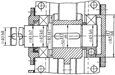
The choice of landings of bearing rings on the shaft and in the housing is carried out in accordance with GOST 3325-85, based on the operating conditions of the assembly unit, which includes bearings. This takes into account: the scheme of operation of the assembly unit (the shaft with the inner ring or the housing with the outer ring rotates); the type of loading of the rings and the operating mode of the bearing.
In practice, most often assembly units containing bearings operate according to the scheme when the inner ring with the shaft rotates, while the outer ring and the housing are stationary (Fig. 50). In this case, it is necessary to ensure the immobility of the connection of the inner ring of the bearing with the shaft. This is achieved through the use of shaft tolerance fields for transitional fits (basic deviations , , , ), which, due to the specific location of the tolerance field of the inner ring (down from the zero line), allows you to get a small, most often guaranteed interference in the connection. An exception is the case when the maximum deviations of the shaft are located symmetrically with respect to the zero line. However, in this case, the probability of getting an interference fit in the joint is quite high (96...98%).
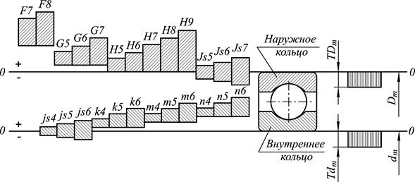
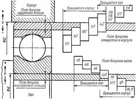
Rice. 50. Schemes of tolerance fields for landing rings of bearings on the shaft and in the housing
when rotating the shaft with the inner ring of the bearing
It is unacceptable to use shafts with tolerances for fixed landings for the connection under consideration, since the interferences obtained in this case greatly complicate the conditions for mounting and dismounting bearings, and during their operation, breakdowns are possible due to significant internal stresses in the rings and balls and jamming of the rolling elements.
The tolerance fields of the shafts, as can be seen from Fig. 50, choose according to the main hole system:
For bearings of accuracy class 0 and 6 − , , , ;
For bearings of accuracy class 5 and 4 − , , , ;
For bearings of accuracy class 2 − , , , .
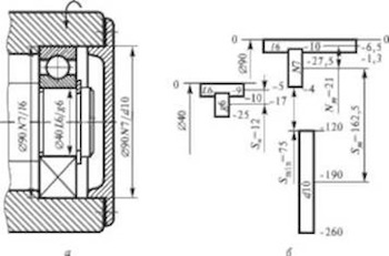
If the outer ring rotates with the housing, while the inner ring and the shaft are stationary, then in this case it is necessary to ensure the immobility of the connection of the outer ring with the housing. The connection of the inner ring with the shaft in this case must be free. Tolerance fields for housing holes and tolerance fields for shafts are given in the reference literature on standardization of bearing accuracy.
The choice of bearing ring fits is also determined by the type of loading and operating mode.
If the assembly unit works according to the scheme, the shaft with the inner ring rotates, and the housing with the outer ring is stationary, two typical bearing loading schemes are possible.
First typical scheme(Fig. 51, A). The radial load is constant in magnitude and direction. In this case, the bearing inner ring experiences circulation loading , and the outer ring local loading.
At local loading (Fig. 51, b) the bearing ring perceives the radial load, constant in direction, only by a limited section of the treadmill and transfers it to a limited section of the housing. Therefore, the mating of the outer ring of the bearing with the housing must be carried out by fit with a small average probable clearance. Due to the presence of a gap, this ring during operation under the influence of individual shocks, shocks and other factors will periodically rotate in the housing, as a result of which the wear of the treadmill will become more uniform and the bearing life will increase significantly.
Circulating loading is created on the ring under a constantly directed radial load, when the loading point sequentially moves around the circumference of the ring with the speed of its rotation (Fig. 51, V). The fit of a rotating circulation-loaded ring must provide a guaranteed interference fit, which excludes the possibility of relative displacement or slippage of the ring and shaft. The presence of the above processes will lead to flaring of mating surfaces, loss of accuracy, overheating and rapid failure of the assembly unit.
a B C
Rice. 51. The first typical scheme of bearing loading and types of loading of gauges:
A - typical loading scheme; b - local loading of the outer ring; V - circulation loading of the inner ring
Rice. 52. The second typical scheme of bearing loading and types of loading of gauges:
A - typical loading scheme; b - oscillatory loading of the outer ring
Second typical scheme(Fig. 52, whose scheme is similar to the scheme shown in Fig. 52, V.
The operating mode of the bearing is taken depending on its design life. With an estimated durability of more than 10000 hours, the mode is considered light, at 5000 ... 10000 hours - normal and at 2500 ... 5000 hours - heavy. Under shock and vibration loads, which are experienced, for example, tram and railway axle boxes, crusher shafts, etc., the mode is considered heavy, regardless of the calculated durability.