Do-it-yourself signaling installation on a car. Typical car alarm connection diagram. Connecting additional equipment
The inviolability of the car and the safety of the property in the cabin are always a concern for car owners. The optimal machine is the connection of the alarm. The shelves of specialized stores are literally bursting with many different models, and the number of manufacturers of car protection products is in the hundreds.
The cheapest and simplest ones do not inspire confidence, but the ultra-modern ones scare with a huge amount of equipment and settings. In addition, there is such an additional complexity as connecting the signaling to central lock, because this attribute is present on most modern cars. The work of two separate systems is aimed at performing protective functions. Their work must be coordinated, for which it is very important to carry out the installation correctly.
How to connect an alarm if the car has a central lock
Central locking is a system for simultaneously locking and unlocking the doors, hood, trunk and gas tank hatch (if it is equipped with such a lock). This feature is very handy. Leaving the salon of old cars, the driver performs a certain ritual - closes the locks on each door, and then checks whether the trunk and hood are closed.
With central locking, this is not necessary. By locking the lock on the driver's door with the key, the driver automatically locks other devices as well. You can control the central locking functions using the button in the cabin and the remote control. The presence of a central lock obliges you to select an alarm of this type, which will be fully compatible with its electrical circuit.
After setting the alarm, its activation should occur simultaneously with the locking of the locks. Similarly, after turning off the alarm, the driver should be able to get into. Installing and connecting an alarm can provide a car with many useful functions. So, for example, a car can:
- automatically close the lowered windows of the doors and the sunroof;
- start and warm up the engine on command from the remote control;
- "hold" the hijacker in the cabin, simulating an engine breakdown;
- make it impossible to start the engine;
- receive and execute commands from the car owner via SMS messages, as well as notify him about the state of the car.
Actually, you can put an alarm on a car at the same time as the central lock, if it is included in the kit. The successful selection of the security system to the brand of the car and its configuration is the key to the success of the event.


Connecting an alarm - procedure
Choosing the right alarm necessary set functions, you can proceed to install it. There are two ways to set an alarm on a car: using the services of a service or an experienced auto electrician; on one's own.
The second option is very risky. Modern alarms are quite complex in the device, they require special skills and knowledge during installation. The alarm circuitry at multiple points will be installed in the vehicle's electrical network. Even an insignificant, at first glance, violation of the circuit can lead to the failure of control units, relays and other elements. Do-it-yourself alarm connection is possible only if the driver knows exactly how to do it and has figured out the installation nuances in advance.
The first step is to determine the installation location of the main parts:
- electronic control unit;
- antenna;
- sensors;
- control panel (if a stationary one is provided);
- sound and light alarms.
Many motorists, when deciding how to connect an alarm, try to make their own design changes to the circuit or connect elements at random. This is unacceptable because the equipment: a) will not work (this is in best case); b) will disable the entire electrical circuit of the car.
The control unit is traditionally installed under the dashboard. Firstly, this place is remote from the eyes and difficult to access. Secondly, all electrical wires are concentrated here, which makes it easier to connect.
At the next stage, the alarm is connected in this order:
- sensors are installed in accordance with the manufacturer's recommendations;
- a sound siren is installed under the hood;
- sensors, light sources, a sound annunciator are connected to the control unit according to the scheme;
- connecting the unit to a power source.
These actions usually do not cause difficulties, since in schematic representation connections are easy enough to figure out. The wiring diagram itself is included in the documentation package for the alarm.
It is quite difficult to connect the alarm with your own hands to the central locking unit. The work is complicated by the fact that the block itself can be installed at a distance from the signaling block, for example, in. Before starting work, you should seek advice from specialists.
The instruction, which is necessarily included in each kit, has general recommendations without taking into account the features of the device of some cars. A similar problem arises when you have to figure out how to connect an alarm with auto start. In this case, the security system unit takes over the functions of the key in the ignition switch and starts the engine on command from the control panel.
Simple rules on how to put an alarm on a car
If the decision has already been made to install the security system on your own, then you should know some rules that should be followed during the work. You need to remember the following:
- each wire is connected to the block or other wire only with the help of terminals or soldering;
- any connector or soldering point must be protected by insulation;
- wiring is laid secretly under the lining with a margin of length, especially at the transition point from the body to the door, trunk, hood;
- when connecting, strictly observe the color of the wires in accordance with the diagram;
- work with the battery completely disconnected.
Following the instructions and recommendations, everyone will be able to put an alarm on the car, which will save on paying for the services of a service center. But in any case, the choice of installation method for the anti-theft electronic system is up to you. If you are not confident in your abilities as an auto electrician, then it is better to go to a car service.
There are various solutions on the market today designed to protect cars from theft. The cost of some of them is comparable to the price of new car. However, do-it-yourself car alarms can be made from any phone capable of making a GSM call. If the circuit is implemented on the basis of the controller, the signaling can even autorun. But adding an autorun option to the car, you need to take care of bypassing the standard immobilizer, and branded devices that allow you to deactivate the immobilizer are expensive. Note that in a scheme where autorun is not used, a standard battery can be removed from the phone. Just such an option is considered further.
Pros and cons of our alarm
The scheme below assumes the use of a phone of the following model: Motorola D520. The features of this mobile device are as follows. When switching on in the absence of a battery, the contacts of the “POWER” button must be kept closed. Only in this case, voltage is applied to the power connector. The call to the last called number is carried out as follows: the “OK” button is pressed 2 times with a time interval of more than 0.1 second. When developing a home-made signaling, which is described below, these features were taken into account.
Mobile phone Motorola D520
The principle of operation of any alarm looks like this: when trying to steal, one of the sensors closes to ground. The following devices can act as a sensor:
- Microbuttons, door and hood limit switches;
- Self-installed secrets (micro buttons);
- Mass-produced modules: shock sensor, tilt sensor, etc.
The contacts of all sensors are connected to one point, while, of course, diodes are used (see fig.).
 Wiring diagram "Logical OR"
 Closing the contact to ground, even if a short time, you will immediately trigger the alarm. Install a volume sensor, and you will protect yourself from theft "one hundred percent".
Each of the active sensors is equipped with a connector, in which one contact is a signal (normally open to ground). And when connecting the "power mass", you need to take care of the quality of the electrical contact, otherwise the circuit will start to work "once".
Self-made car signaling
The connection to the signaling of sensors that prevent theft was discussed in the previous chapter. Some cars have mics that close when the door is closed, and then you need to use an additional relay. Remember: you need one contact shorted to ground at the time of the alarm. You will also need a secret, that is, a toggle switch connected in series with the signal contact. The toggle switch will allow the driver to turn off the protection himself. If it is not turned off, calls will be made all the time (with a period of 100 seconds).
Basic option (most difficult)
See what the main connector of the phone looks like if we talk about the D520 model:
 Motorola D520 connector diagram
 Here you will need the power pins (1 and 2), so use a separate connector installed on the case. To get to the board with buttons, the phone case is dismantled. It is necessary to solder 3 wires to the contacts of the "OK" button, and the "POWER" button is short-circuited. The battery must be removed before soldering. Further, the battery is not used at all.
Homemade signaling contains only common elements in its design. Two wires (contacts "+" and "-") are connected to the phone's power connector, three more - to the "OK" button:
 Appearance details BA2
 Place the speaker next to the handset of the mobile device. Here are the options on how to do it:
- The microphone is placed in the muffler, but the speaker is not used (then the VT4 transistor is excluded);
- The second option - the speaker is used, but the microphone is located in the cabin.
If the microphone is not needed at all, the DA2 amplifier is excluded, and at the same time a pair of transistors (VT3, VT4). A simple circuit thus contains two "field workers" and "logic". Next, we consider what needs to be done to simplify the circuit even more.
Simplifying the circuit by 2 times
The presence of the option to respond to sound reduces the likelihood of theft. An intruder does not have to open the door to get into the salon, usually they break the glass. When you buy an external sound sensor, you will notice that it uses less simple circuit than has been considered. To get rid of unnecessary details, it makes sense to do the following.
 DC stabilizer 7805
 We evaluate the result from the side
At one time, when there were no immobilizers yet, the drivers themselves installed various secrets in the cabin. The engine could be started by someone who knew where to bring the magnet or where the toggle switch was located. But it turns out that even the car owner himself had to make too many movements, otherwise the car remained in place. Protection technologies developed slowly, and no one could offer an alternative even in the 90s.
Secrets will not be useful if an attacker finds out about their presence and location. But the immobilizer also prevents the engine from starting, only it is controlled not by a toggle switch, but by a radio key fob. Now it is almost impossible to select a key fob, but grabbers are used, and sometimes successfully. However, protecting even a modern car from theft, no one forbids the use of several solutions.
 Valet button of modern alarm
 Do-it-yourself security alarm is made in a couple of hours. And you can install it even faster. A simple signaling, of course, will not save you from theft in 100% of cases. In addition, the owner will have to switch the toggle switch as soon as he is in the cabin.
If the switch is not made, wait for the balance to be reset on your D520. And yet, the car will be able to move, even if the contacts SB1 are not open. The immobilizer, if installed, will also not interfere with movement. It turns out that the considered solution is better than the usual secret. But its cost is also higher.
Homemade signaling from Nokia
Purpose of connectors and their contacts

Assignment of the pins of the "X4" connector


Connecting car alarm power circuits
To connect the power circuits, two wires are used: +12 V and ground (red and black alarm wires).
First of all, connect the ground wire of the car alarm. To connect to the ground (black wire of the 16-pin connector "X3"), it is recommended to use a standard bolt (nut) of the ground. At the same time, at the end of the wire, it is necessary to crimp the terminal under the corresponding bolt. It is forbidden to connect the ground wire to the body with a self-tapping screw due to insufficient connection reliability. When using a standard bolt or nut, make sure that there is no plastic between the ground wire terminal and the body. For example, if a bolt fastens a dashboard element to the body. In the presence of plastic, the contact will not be reliable, which can lead to engine blocking and damage to the alarm. If the ground connection is made under the hood, it is recommended to treat the junction with an anti-corrosion compound.
To connect +12 V (red wire of the 16-pin connector "X3"), you must select a regular wire of the appropriate section (at least 2 mm2) or connect directly to the battery. When connecting to a standard electrical wiring wire, it is necessary to take into account the rating of the standard fuse. Can be connected to the power wire of the fuse box, body control module (BCM), or ignition switch.
When connecting directly to the battery, it is necessary to install a 15A fuse in the red wire circuit no further than 40 cm from the "+" battery terminal.
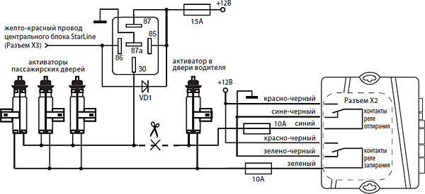
Connection to the central locking system
The car alarm has built-in central lock control relays. The relay contact circuits are connected to the 6-pin "X2" connector. The load capacity of the built-in relays is 15 A. The duration of the control pulses is programmable (function 1).
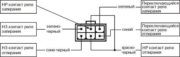
Wiring diagram for locking system with positive or negative control

Wiring diagram for two-wire locking system drives

Wiring diagram for pneumatic locking system

Wiring diagram for driver's door actuator for two-step door unlocking
To implement this function, it is necessary to program the two-step door unlocking function (function number 15, mode 1).
Connecting the engine interlock circuits
Connecting an external engine blocking circuit using conventional relays
Break one of the standard circuits for ensuring the operation of the engine and connect an additional relay to the circuit break. The type of contacts of the interlock relay NO (normally open) or NC (normally closed) is programmable (function 10). Factory setting - NC type of relay contacts. An example connection is shown in the figure below:
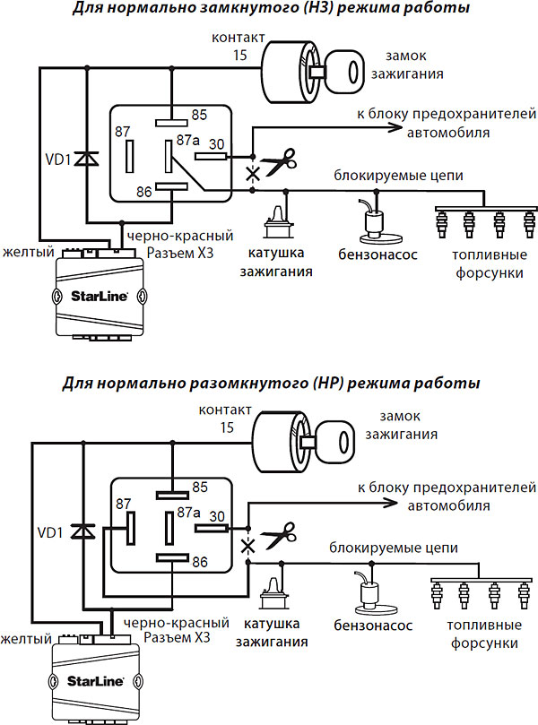
Connecting the built-in engine blocking circuit
On the board of the central signaling unit, a blocking relay with one group of switching contacts is installed (connector "X1"). The maximum switched current of the built-in blocking relay is 15A. Be sure to program the required relay operation mode - programmable function 10. factory setting- NC blocking. Break one of the regular engine blocking circuits, for example: power to the fuel pump or fuel injectors. Connect two of the three changeover contacts of the built-in interlock relay into the break of the blocked circuit. Use the blue and blue/white wires from the alarm kit.
Attention! When connecting the blocking to an open circuit with an inductive load (blocking the power wire of the fuel pump), it should be remembered that the maximum current of this circuit during switching may exceed the permissible current of the relay, which will lead to its failure after a while.
Connecting limit switches
Door switches
When installing a car alarm, you can connect the alarm inputs directly to the door limit switches or to the interior lamp as follows:
- Connect the blue-black wire of the 16-pin connector "X3" to the push-button switches of the doors, which close to the body when the doors are opened.
- Connect the blue-red wire of the 16-pin connector “X3” to the door push-button switches that close to +12 V when the doors are opened.
In a number modern cars there is a survey of electrical equipment by standard systems and in this case it is necessary to use diode isolation. If the car has courtesy interior lighting, it is also necessary to use diode decoupling.

Attention!

Attention! As VD1-VD4, we recommend using diodes of the 1N4007 type or similar.
Diodes VD5-VD8 must be rated for the appropriate current, which is determined by the number and power of interior lighting lamps.
Hood limit switch
Connect the orange-gray wire of the 16-pin connector “X3” to the hood limit switch, which closes to ground when the hood is opened. In the absence of a regular limit switch, it is necessary to install it (included in the delivery set).
Trunk limit switch
Connect the orange-white wire of the 16-pin connector “X3” to the trunk limit switch, which closes on the body when it is opened.
Light signaling connection
In cars where only two wires are used in the standard electrical equipment of the car for direction indicators, it is possible to directly connect the car alarm outputs:
- Connect the green-black wire of the 16-pin connector “X3” to the direction indicator lamps (one side). Maximum load current 7.5 A.
- Connect the green-yellow wire of the 16-pin connector “X3” to the direction indicator lamps (other side). Maximum load current 7.5 A.
If more wires (4 or 6) are involved in the standard wiring of the car for the direction indicators, then it is necessary to use a diode decoupling:

Attention! Diodes VD1-VD6 must be rated for the appropriate current, which is determined by the power of the direction indicator lamps (at least 3A is recommended, for example 1N5401).
Siren connection
To connect the siren, a gray wire is used (16-pin connector "X3") - a positive siren control output. Maximum load current 2 A.
The volume of the short acknowledgment beeps emitted by the siren can be adjusted using function 6. To decrease the volume of the siren, program option 2 or 3 of function 6. Selecting option 4 will disable the acknowledgment tones.
Attention!
- This function can NOT be implemented when using a stand-alone siren.
- If the siren will not sound when choosing options 2 or 3, then install an additional diode in the siren circuit as shown in the figure:

When connecting the siren ground wire, it is necessary to ensure reliable contact.
Connection to parking brake or brake pedal
The orange-violet wire of the 16-pin connector "X3" must be connected to the parking brake (for manual transmission) or to the brake pedal (for automatic transmission).
When connecting to a parking brake, it is necessary to connect the diode to the break of the standard wire of the parking brake and connect the car alarm input between the diode cathode and the limit switch.


Connecting additional channels
Additional channels (outputs) can be used to expand the security and service functions of the car alarm. Some typical use cases for additional channels are listed below.
When using additional channels, it should be remembered that they use an “open collector” type of circuitry, and the maximum allowable current is 200 mA per channel.
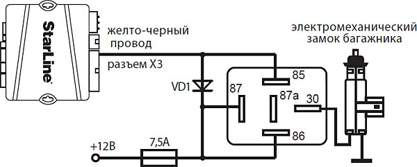
Additional channel 1 - connection to the electric trunk release
Attention! The alarm has an output for remote unlocking of the trunk (yellow-black wire). An additional relay must be used when connecting. An example of a connection diagram is shown in the figure below:
Additional channel 2 - two-step door unlocking
To implement two-step door unlocking, it is necessary to connect the output of additional channel 2 (yellow-red wire of the 16-pin “X3” connector) according to the diagram.
Additional channel 3 - ignition support
Additional channel 3 can be used to implement the protection function with the engine running.
Scheme of +12V support at the ignition switch when the engine is running in armed mode with the engine running and in turbo timer mode:

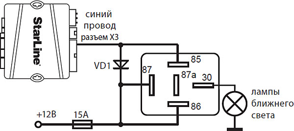
Additional channel 4 - connection to interior lighting and implementation of the "light path" function
The car alarm has an output that can be used to connect to the interior lighting and implement the “polite interior lighting” function (blue wire of the 16-pin “X3” connector). An additional relay must be used when connecting.
Diode VD1 must be rated for the appropriate current, which is determined by the power of the interior lighting lamps.

Additional channel 4 can also be used to connect to the low beam headlights and implement the "light path" function. An additional relay must be used when connecting. An example of a connection diagram for channel No. 4 (blue wire of the 16-pin “X3” connector).
Connecting the shock sensor and additional sensors
The two-level shock sensor included in the delivery set is connected to the 4-pin connector “X9” of the central unit.
An additional sensor is connected to the 4-pin connector "X7" of the central unit. After connecting the additional sensor(s), it is necessary to program function 12 of the programmable function table according to the required signal processing algorithm. An inclination sensor or a microwave sensor can be used as an additional sensor.

First you need to reduce the sensitivity of both levels of the sensor by turning the sensitivity knobs counterclockwise until it stops.

The warning level is set first. To configure, you need to open the car door, turn on the security mode. Then alternately turning the adjusting screw of the warning level of the sensor clockwise and applying light blows to the car body (for example, at the junction of the side door window frames) to achieve the desired response threshold. Then you need to set the alarm level of the shock sensor in the same way.
Service button connection
Connect the service button to the 2-pin connector "X6" of the central unit.
Connecting the LED - status indicator
The LED indicator must be connected to the 2-pin connector "X7" of the central unit.
Connecting the transceiver (antenna module)
The transceiver module with antenna is connected to the 5-pin connector "X4" using the cable included in the alarm kit.
Connecting additional equipment
Connection of StarLine security and search modules
GSM modules StarLine Space, StarLine Messenger M20 and StarLine Messenger GPS M30 are connected to the blue 3-pin connector “X8” of the central unit using a special cable (included in the delivery kit of the modules).
Connecting radio relay R2
In total, 2 digital StarLine R2 engine blocking radio relays can be written to the alarm memory.
The wiring diagram for digital engine blocking radio relays is given in the instructions for installing the relay included in its kit. Before connecting the digital StarLine R2 engine blocking radio relay, you must select one of the radio relay operation modes (determined by the state of the wire loop coming out of the radio relay board: a whole loop - NC mode, open - NO mode) After connecting the relay to the vehicle circuits, it must be written to the alarm memory in according to the algorithm below:
- Enter the programming mode of security and service functions in the car alarm, and depending on the desired mode of operation of the relay, select option 3 or 4 of function 10, respectively. Switch off the function programming mode.
- Connect the black wire labeled "MAC" to the body of the vehicle.
- With the ignition off, press the service button 7 times.
- Turn on the ignition. 7 siren signals will sound, confirming the entry into the recording mode of the radio relay.
- Within 5 seconds, connect the black wire of the radio relay labeled "FIRE" to the ignition circuit. In confirmation of the successful recording of the first radio relay R2 in the alarm memory, one long siren signal will follow.
- To exit the keyfob recording mode, turn off the ignition, or wait 5 seconds, then the system will exit automatically. If necessary, write down the second radio relay in the same way. In confirmation of the successful recording of the second radio relay R2 in the alarm memory, 2 long siren signals will follow.
If, when trying to record the radio relay, 3 long siren signals sound in response, this means that the radio relay has already been recorded in the system memory.
The StarLine R2 relay, previously written to one alarm block, cannot be written to another block without a preliminary reset.
To reset, do the following:
1. Before applying power to the relay, close the contact pads, as shown in the figure:

2. Apply power to the relay for 10 seconds, turn off the power, open the contact pads - now it can again be registered in the car alarm.
Typical car alarm connection diagram

If you are the owner expensive car then most of all this article is not for you. And if you have a rather modest car and you want to protect your car at minimal cost (which is not at all proportional to the quality), then this description is for you.
The fact is that car alarm should not cost more than 5% of its market value, which for a used car is the amount for which you cannot buy a ready-made, more or less reliable, alarm system. The danger for a car without an alarm is not only in its theft, but also in the very penetration into the salon, theft of property, documents, etc., which is very common in the current conditions.
The damage may be small, or it may exceed the value of the car itself. In the traffic police, such cases are often not considered at all, since there is little evidence for them and they don’t initiate a case at all, stating that you yourself forgot your purse or documents somewhere, but you didn’t have any money at all. My friends had several similar cases, although the cars were equipped with purchased alarms.
But the fact is that scammers and thieves have long learned to bypass not expensive (although this is for someone), and rather monetary standard alarms. And it has become much easier to open (steal or rob) a car equipped with such a standard purchased alarm system. Now there are many different scanners with which an attacker reads your alarm code when you arm your car by giving a command over the radio from the key fob.
That's it, the "bad person" already has your code and he can easily both open the car and close it without attracting attention at all. Further, I think everything is clear to everyone. Therefore, having such an alarm, you significantly increase the potential theft or theft from the car, even compared to if you just locked it with a key, without the possibility of remotely opening the doors. And if we also take into account the human factor, the master who installs the alarm for you can naturally know how to turn it off, make a duplicate, etc.
Of course, most masters are decent people, but the facts show that if there is an opportunity, then someone will always take advantage of it. Data can be transferred to interested parties and "shoot" in a year or two after the installation of the alarm. It will be almost impossible to tie this into one whole, and even more so to prove it.
There are many more arguments not in favor of standard low and middle-class purchased car alarms, not to mention the costly part.
Consider the functions that a simple, inexpensive do-it-yourself car alarm should perform:
- The alarm should respond to penetration into the car, for example, using an IR motion sensor, or from standard light buttons that are triggered when a door or trunk is opened (the cheapest option, easy to implement, but nevertheless quite functional).
- An intrusion alarm should notify with a sound, a regular signal or an additional siren. This notification should last a certain time, for example two to five minutes, and then automatically turn off.
- After the alarm is triggered, the system should switch to the unauthorized entry mode - it should work repeatedly, block the engine start, etc.
- - The car alarm must consume low current, excluding the discharge of the battery (regular or additional) during the long-term parking of the car on guard.
- The mechanism of inclusion, transfer to the mode of protection and deactivation of the alarm system. IN simple case, a short delay (5-10s), after turning on the hidden toggle switch, while leaving the car and closing the door.
- Easy to manufacture and connect with low financial costs with maximum efficiency.
Such an alarm system will reliably protect even such a work as the Six-wheeled "Cossack Hammer"
Below is one of the most simple circuits car alarm which you can make yourself.

The car alarm combines an acoustic alarm that is triggered by the short circuit of the sensors (buttons for turning on the light of the doors and trunk) and when the ignition is turned on and blocks the engine from starting.
This scheme is suitable for installation on domestic cars equipped with a classic contact ignition system (VAZ, Moskvich, Volga, etc.) and any foreign ones with a similar contact ignition system. (Previously, all cars had a contact ignition system - they turned the key - the contacts closed), Installation is also possible in many new cars.
Homemade car alarm scheme quite simple and understandable to any novice radio amateur. All details are public and cost a penny. Connection in wiring diagram car is also shown in the diagram. The bold line highlights the signaling unit itself, which is assembled in a small plastic case, selected from those available or can be purchased on the radio market - to your taste.
Everything outside the bold rectangle is the electrical equipment of your car, as well as others additional elements, which are entered into the car circuit (Sensors K2 and KZ, two relays P1 and P2, toggle switch 51).
Two types of contact sensors are used - regular interior lighting switches located in the car doors (they are connected in parallel, so the diagram shows one K1 sensor and one H1 lighting lamp), and specially installed sensors (door type) under the hood and trunk lid, if the trunk not equipped with a regular switch, similar to a door switch - so that when closed, their buttons are pressed and the contacts are open. When opening, the contacts must close.
As a source sound signal car alarm system, you can use the standard signal of your favorite car or an installed purchased siren. The signal is switched on using an additional electromagnetic relay of sufficient power (since the current passes through the signal coil), which must be installed in the engine compartment of the car - P1. The same P2 relay is used to block the ignition system. In principle, this relay can be placed in the box of the alarm itself. Its winding is connected in parallel with the winding P1 and when the alarm relay P2 is triggered, it shunts the capacitor C of the ignition system with its contacts, which makes it impossible to spark and start the engine.
The car alarm is activated using the micro-tumbler 51, which must be installed in a "secret place" inside the car (usually somewhere under the panel), known only to you and authorized persons. After turning on the power, the device will not respond to the status of all sensors for 15-20 seconds. This time is allotted for getting out of the car and closing the doors. After this time, the car alarm goes into armed mode.
To increase reliability, you can use an independent additional small battery, this is at will, desire and financial capabilities.
Even without an independent power supply, such an alarm in modern conditions it will be more reliable than a simple purchase with a remote control. About the cost is clear and so.
The system is economical. In standby mode, it consumes less than 0.7 mA, the trigger mode is 1.1 mA, and the current of the signal or siren is 0.2-0.5 A
Additionally, you can add an infrared motion sensor - purchased or if one was lying around on the farm.
If the sensor for 220V must be converted to 12V (8-20 Volts). A standard household motion sensor must be opened. The spherical part is removed by bending one support. The halves are fastened with latches.
Pull out the fee. The sensor is a passive IR receiver that responds to changes in the IR radiation that hits it. Typically, the motion sensor's field of view is 180 degrees.
Another simple car alarm circuit without chips

The circuit works on a similar principle, using the same sensors as in the previous case.
Short description:
SA2-SAn - intrusion sensors (door buttons, etc.). Diodes VD5-VDn are used to isolate the sensors if they are used for other purposes. If the sensors are only for signaling, diodes can be excluded.
The supply voltage supplied from any closed sensor, through R1 C1 is supplied to VD1. The R1 C1 circuit creates a short current pulse even if the sensor is left closed. Capacitor C2 prevents the alarm from triggering when the SA1 toggle switch is turned off.
The output key and multivibrator are assembled on the elements C4, R4, R5, VT2, K1. The duration of K1 being in the on position is determined by the selection of resistor R5 (you can install a variable resistor), and in the off position - R4. The overall pulse frequency is set by C4. This part of the circuit requires more careful tuning. Approximately around 2 Hz.
On elements C3, VD3, VD4, a node is assembled, which forms a delay in the alarm operation when the intrusion sensor is closed. This is necessary to delay the operation of the siren when the owner opens the car for 4-8 seconds to turn off the device (so as not to scare others :-)). The duration of the delay is set by the capacitor C3. The discharge of the capacitor when the power is turned off is provided by the resistor R3.
In this scheme, there is no node that would turn off the alarm after a while, this is the simplest option. If desired, such a node can be modified by slightly complicating the design, or you can use an autonomous time relay with periodic reset.
VD1 - any low-power thyristor, for example KU101. You just need to select C1 (increase if the alarm does not work when the sensor closes), R2 (decrease if it does not work) and C2 (increase if it works immediately when the circuit is turned on). Diodes - any low-power. Relay K1 - RES55A, or similar (selected according to the power of the switched current of the siren-signal). If you use a more powerful relay (more than 1A), then you will need to increase the capacitances of the capacitors C3 and C4 quite a lot (this will lead to an increase in the size of the device). Therefore, if you have a fairly powerful load, it is better to connect a powerful relay to the RES55A output. Transistors - also any, with the appropriate transition structure, and VT2 must withstand the relay turn-on current. SA1 - any small switch (tumbler).
To turn on the car alarm:
1. Turn on the SA1 toggle switch with the sensor closed (with open door). In this position, the circuit will not turn on and can be indefinitely.
2. Close the door - the circuit switches to armed mode.
To turn off the car alarm:
1. Open the door (this will close the intrusion sensor).
2. Fast, within 8-10 sec. disarm - turn off the SA1 toggle switch.