Repair of the front axle on the UAZ. Competent repair of the front axle UAZ "loaf. Bridge removal procedure.
Many Internet users in Yandex or Google enter a similar request - “repair front axle UAZ 469. This means that they are interested in how to repair the front or rear axle on the Oise themselves. Of course, the procedure for disassembling and repairing the bridge is described in special books on repair and operation, which are not a problem to get now. However, to disassemble with your own hands what is the front, what is the rear axle to the last screw is, to put it mildly, not an easy task. It may turn out that you just need to replace some small part, to access which you do not have to disassemble everything.
Front axle UAZ 469
Here are just a few possible options breakdowns of bridges on the UAZ 469 (Hunter, Patriot, "loaf"):
- Worn differential, bent gearbox housing
- Critical wear of the main gear in the gearbox
- Wear of the steering knuckle (ball joint, trunnion) on the front axle
- The appearance of large gaps in the pivot joints
- Bearing wear resulting in the need for adjustment/replacement
- Injection of elements requiring lubrication
It can be difficult to understand which of the above happened to your car, however, it is often possible even by ear to approximately localize the problem. If increased noise is heard from the front or rear axle, a hum (even in neutral gear) - the gearbox is most likely worn out (repair is required), or the bearings require lubrication. If your car "scours" from side to side and at the same time steering in order - the problem can sit in the trunnion, CV joint or in the incorrect installation of the pivots that fix the ball joint, as a result of which there is a backlash and the wheel starts to “walk”.
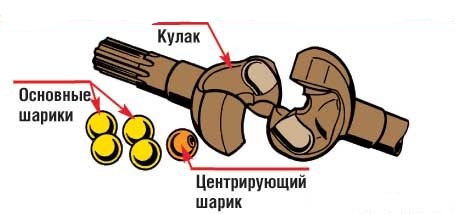
What is the SHRUS made of?
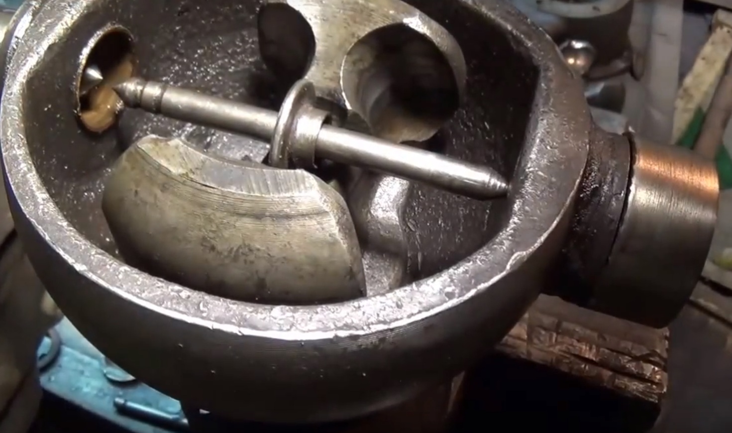
A very common malfunction is the departure of ball bearings that are in the CV joint. They fly out just because of the incorrect adjustment of the pivots, as a result of which the geometric center of the CV joint and the trunnion do not match. As a result, the axle shaft "walks" in the seat and gradually breaks. The joint itself is also damaged. And when turning from the side of the wheel, a crunch is heard and at the same time the wheel can wedge. Some masters in the process of repair simply throw out all the balls, except for the centering one (additionally welding it) - in order to get rid of the problem of their constant flying out.
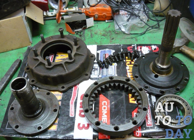
Swivel fist of the front axle UAZ 469 assy
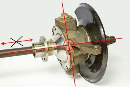
But this does not save for long, there are even cases when the welded ball breaks off during the ride, the loads are so high there. It is much more effective to do the adjustment of the pivots. It is necessary to achieve such a state in which the line passing through the pivots and the center of the axle shaft will intersect at one point. And it is at this point that the center of the CV joint should be located. The displacement of the axle shaft to the left and right, as shown in the figure, is unacceptable, it must be rigidly fixed; for this, thrust rings and bushings are provided in the design.
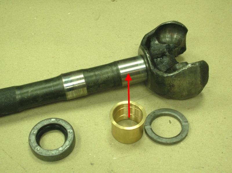
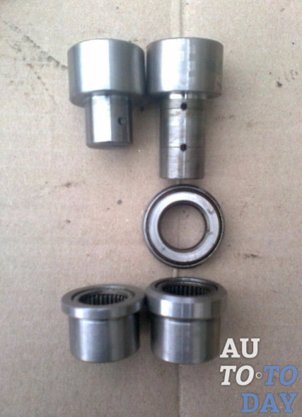
Bushing seat
Important! In order for the halves of the joint to be connected tightly, it is necessary to put bronze bushing. If this is not found in the store, you can put, for example, the connecting rod bushing of the T-40 tractor. Cut it on one side and remove the excess metal a little bit until it fits snugly into the hole (in the steering knuckle). Then it is necessary to adjust the sleeve to the diameter of the axle shaft with a 32 reamer. If this is not done, the balls in the CV joint will still fly out.
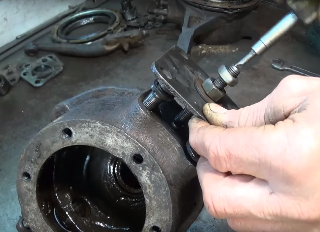
Removing the kingpin
And now we will consider the process of removing the kingpin on the UAZ 469. For this procedure, you can use a special puller, however, it is quite possible to make it yourself. All you need is a plate with a bolt hole, a washer and 2 nuts. The plate will rest against other bolts around the perimeter, and the center bolt will just pull the kingpin out of the seat.
King pin pressing process
Adjustment
Before you start adjusting, prepare everything you need: bushings in the trunnion (if there is a working on the trunnion), thrust bushings 4 pieces, as well as oil seals. The main condition for adjustment is that the two halves of the CV joint do not dangle, as with rectilinear motion, and when turning! The procedure is as follows:
During the assembly process after repair, it is necessary to lubricate all the bolts with nigrol so that the next time everything is easy to unscrew. All mating surfaces (the junction of the trunnion and the steering knuckle housing) must be cleaned of dirt. It is not recommended to lubricate the CV joint with grease, as it is thick. When heated under the action of centrifugal force, the entire grease will scatter along the walls of the ball joint, but it is necessary that the CV joint balls are abundantly lubricated. To do this, it is recommended to dilute the grease by half with nigrol.
After the final assembly and repair, one more important adjustment needs to be made. It's about about the adjusting screw. This is the bolt that limits the maximum angle of rotation of the wheel. It is important not to overdo it, do not tighten the bolt all the way - otherwise the wheel will wedge. Tighten almost to the end, and then try to turn the wheel (more precisely, the shaft on which it will stand). It is necessary to unscrew the bolt back until the wheel stops wedge. In this case, the angle of rotation should not be lower than the factory one. Well, now you yourself can repair the front axle on 469 UAZ!
P.S.: on the back - there is nothing special to break, since there are no turning parts (knuckle, CV joint). Just periodic maintenance, lubrication of parts - and it will go for a long time. The maximum that can break is the gearbox. In general, UAZs, and specifically 469 UAZs, were produced with the so-called "military" bridges, which were distinguished by greater reliability and maneuverability. Therefore, many owners of tuned UAZs put them on themselves.
POSSIBLE FAULTS OF THE FRONT AXLE, THEIR CAUSES AND METHODS OF ELIMINATION
The main gear and differential of the front axle are similar in design to the rear axle. All maintenance and repair instructions for the rear axle also apply to the front axle.
|
Rice. 3.98. Rotary fist: a - signal groove; b - pointer; I - right rotary fist; II - left rotary fist; III - wheel off clutch; IV – wheel disconnection clutch (option); c - the wheels are disabled; g - wheels are included; 1 - steering knuckle lever; 2 - axle housing; 3 - stuffing box; 4.20 - gaskets; 5 - ball bearing; 6 – the case of a rotary fist; 7 - support washer; 8 - overlay; 9 - kingpin; 10 - grease fitting; 11 - locking pin; 12 - trunnion; 13 - wheel hub; 14 - leading flange; 15 - clutch; 16 – clutch bolt; 17 - lock ball; 18 - protective cap; 19 - kingpin bushing; 21 - inner clip; 22 - ring-partition; 23 - outer clip; 24 - rubber sealing ring; 25 - felt sealing ring; 26 - thrust washers; 27 – a bolt of restriction of turn; 28 - emphasis-limiter of rotation of the wheel; 29 - ring; 30 - leading slotted sleeve; 31 - connecting slotted sleeve; 32 - leading sleeve; 33 - cap; 34 - cover; 35 - cuff; 36 - pin; 37 - switch; 38 - ball; 39, 41 - springs; 40 - gasket; 42 - driven bushing; 43 - extension spring; 44 - body; 45 - locking ring |
Maintenance
During maintenance of the front drive axle, check and, if necessary, adjust the tightness of the kingpin bearings, wheel toe and maximum steering angles, check and tighten the fastening of the steering knuckle lever, flush and change the grease in the steering knuckles. When inspecting the steering knuckles, pay attention to the serviceability of the stops-limiters 28 () of the rotation of the wheels, the adjusting bolts 27 and the reliability of their locking.
Check and adjust the axial clearance of the pivots on the car in the following order:
1. Brake the vehicle with the parking brake or place chocks under rear wheels.
2. Jack up the front axle.
3. Turn away nuts of fastening of a wheel and remove it.
4. Turn away bolts of fastening of an epiploon of a spherical support and move aside an epiploon.
5. Check the axial clearance of the pivots, for which, shake the steering knuckle housing up and down with your hands ().
6. Turn away nuts of fastening studs of the lever 1 (see) of a rotary fist or bolts of fastening of the top lining 1 (see) and remove the lever or the top lining of the pivot.
7. Remove the thin (0.1 mm) shim and install the lever or trim in place.
8. Unscrew the fastening bolts and remove the bottom pad of the 4th kingpin, remove the thin (0.1 mm) shim and install the kingpin pad in place.
To maintain the coaxiality of the hinge, remove the gaskets of the same thickness at the top and bottom.
Check the build results. If the gap persists, readjust by removing thicker shims (0.15 mm).
Large wear of the pivots 9 and bushings 19 (see) in diameter causes a violation of the camber angle of the wheels, their "wobble" when driving and uneven tire wear. In this case, replace worn parts.
Check the maximum angles of rotation of the wheels on a special stand (). The angle of rotation of the right wheel to the right, and the left wheel to the left should be no more than 27 °. Adjust with bolt 27 (see).
Adjust the wheel alignment by changing the length of the tie rod. Before adjustment, make sure that there are no gaps in the steering rod joints and hub bearings; then, loosening the lock nuts (having right and left threads), turn the adjusting fitting to set the required wheel toe-in.
Toe-in at normal pressure in tires should be such that size A (), measured along the center line of the side surface of the tires at the front, is 1.5–3.0 mm smaller than size B at the rear.
After adjustment is complete, tighten the lock nuts. Tightening torque 103–127 N m (10.5–13 kgf m).
Toe-in can be checked with a model 2182 GARO ruler.
Repair
To carry out repairs, remove the front drive axle from the vehicle and disassemble.
After disassembling and washing the parts, check their condition and determine their suitability for further work.
Repair the crankcase, main gear and differential in accordance with the instructions set out in the "Rear Axle" section. When bending the axle housing, edit it in a cold state. Replace worn steering knuckle parts with new ones using the data.
Remove the front axle in the following order:
1. Install blocks under the rear wheels of the car.
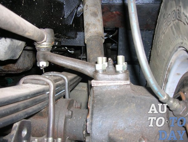
2. Disconnect the hydraulic brake lines on the left and right side members from the flexible hose going to the front wheel brakes. Loosen the nuts securing the flexible hoses and remove them.
3. Turn away nuts of fastening of the lower ends of shock-absorbers.
4. Turn away bolts of fastening of a forward propeller shaft to a flange of a leading gear wheel.
5. Loosen and remove the bipod ball stud nut, disengaging the link from the bipod.
6. Turn away nuts of fastening of step-ladders of forward springs, remove linings, step-ladders and slips. Raise the front of the car by the frame.
Disassembly of the front axle
Disassemble the front axle in the following order:
1. Install the axle on the stand, unscrew the wheel nuts and remove the wheels.
2. Loosen and unscrew the nut securing the bipod link pin to the steering knuckle arm and remove the bipod link.
3. Turn away screws and remove brake drums.
4. Remove wheel disconnect couplings.
5. Straighten the bent edges of the lock washer, unscrew the nut and locknut, remove the lock washer and the inner ring with rollers of the outer bearing of the right and left wheel hubs.
6. Remove the wheel hubs.
7. Turn away bolts of fastening of brake boards, remove boards, pins of rotary fists and take out hinges of rotary fists.
Dismantling of UAZ-469, UAZ-31512, 31514 axles includes operations for dismantling the wheel reduction gears of the rear drive axle, main gear and differential, drive of the driven drive wheels of the front axle.
It is recommended to disassemble the wheel reduction gears of the rear axle UAZ-469, UAZ-31512, 31514 in the following sequence:
Unscrew the fitting of the brake hydraulic drive pipeline from the wheel cylinders and remove the pipeline, then unscrew the nuts securing the drive flange, remove the washers and remove the flange using dismantling bolts (it is not recommended to unscrew the studs from the wheel hubs);
Unbend the tab of the lock washer, unscrew the lock nut and remove the lock washer, unscrew the bearing adjustment nut and remove the thrust washer, hub with drum, bearings, stuffing box and stuffing box thrust washer;
Unscrew the trunnion fastening nuts, remove the washers, oil deflector, oil deflector gasket, trunnion, trunnion gasket, spring gasket, brake assembly, brake shield gasket;
Unscrew the nut of the driven shaft of the UAZ-469, UAZ-31512, 31514 reduction gear, unscrew the bolts securing the wheel gear case cover, remove the wheel gear housing cover assembly with the driven shaft, remove the cover gasket and press the drive shaft of the gearbox from the cover;
Straighten the bent edges on the washers of the driven gear mounting bolts, unscrew the bolts and remove the gear from the shaft;
Mark the position of the roller bearing housing on the crankcase lug, straighten the bent edges of the lock washer of the bearing housing mounting bolts, unscrew the bolts and remove the bearing housing, remove the ball bearing circlip, axle shaft and oil deflector from the wheel gear housing, then remove the roller bearing circlip, roller from the axle shaft. bearing, pinion gear and ball
bearing.
It is recommended to disassemble the main gear and differential of the rear axle reducer UAZ-469, UAZ-31512, 31514 in the following sequence:
Unscrew the nuts securing the crankcase cover and remove the washers, the cover with the axle shaft housing and gaskets, remove the differential with the driven gear assembly from the crankcase, unpin and unscrew the flange fastening nut on the drive gear and remove the flange;
Press the drive gear with the inner ring of the large bearing, spacer sleeve, shim and spacers out of the crankcase, remove the stuffing box, thrust ring and inner ring of the small bearing from the crankcase;
Remove the gaskets, adjusting washer, spacer sleeve from the drive gear of the final drive reducer UAZ-469, UAZ-31512, 31514, press the inner ring of the bearing and remove the adjusting ring, then press the outer rings of the bearings out of the crankcase and cover, remove the inner rings of the bearings and adjusting gaskets from the box of satellites;
Straighten the antennae of the lock washers, unscrew the bolts of the driven gear and remove the driven gear, then straighten the antennae of the lock washers and unscrew the bolts for fastening the halves of the satellite box, disconnect the right half of the satellite box from the left and remove the differential gears, pinion axles and support washers.
Picture 1
The drive of the driven drive wheels of the front axle UAZ-469, UAZ-31512, 31514 should be disassembled in the following sequence:
Unscrew the nuts securing the ball pins of the tie rod ends and remove the tie rods, unscrew the protective cap of the wheel disconnect clutch and
remove the shut-off clutch by unscrewing the bolt 26 (see Fig. 1);
In accordance with the instructions for disassembling the rear drive axle wheel reduction gears, remove the drive flange, hub with drum and bearings, trunnion, brake assembly, wheel reduction gear cover with driven shaft, remove the shaft from the cover and remove the gear from the shaft.
Unscrew the bolts securing the ball joint of the pivot pin UAZ-469, UAZ-31512, 31514 to the axle housing and remove the stops-limiters of the rotation of the wheels and the pivot pin assembly;
Unscrew the nuts from the studs of the lever on the left body of the pivot pin or the bolts of the upper kingpin lining on the right, remove the lever with expanding bushings (or the upper lining) and the set of shims, remove the lower kingpin lining and the set of shims;
Unscrew the bolts securing the gland of the ball joint and the body of the stub axle UAZ-469, UAZ-31512, 31514 and remove the clips, the felt ring and the gland seal with the spring assembly;
Remove the pivots using a puller and remove the stub axle housing with the joint assembly, press the oil seal out of the ball joint, remove the joint with the drive gear and bearings as an assembly. Without special need, it is not recommended to unscrew the bolts of the roller bearing housing and remove it;
Loosen the roller bearing fastening nut on the pivot shaft, remove the roller bearing, pinion gear, ball bearing cup and ball bearing.
Disassemble the constant angular velocity joint (CV joint) UAZ-469, UAZ-31512, 31514 only if necessary in the following order:
Mark with paint the mutual arrangement of the fists of the hinges and spread the fists. To do this, you need to knock with a fork of a short fist on the corner of a wooden stand;
Clamp the hinge in a vice by the long fist with the short fist up and turn the short fist towards one of the peripheral balls. If at the same time the opposite ball does not come out of the grooves, it is necessary to press or hit the short fist with a copper hammer.
When doing this, be careful, as one of the balls can fly out of the hinge at high speed. After that, remove the rest of the CV joint balls UAZ-469, UAZ-31512, 31514.
The dismantling of the UAZ-469B axles is carried out in the same sequence as the UAZ-469, UAZ-31512, 31514 drive axles.
A feature of disassembly is the pressing out of the drive gear of the final drive from the axle housing. For this purpose, a puller is used. The rest of the operations when disassembling the front to rear drive axles of the UAZ-469B do not cause difficulties.
After disassembling the UAZ-469, UAZ-31512, 31514 bridge and cleaning its parts, it is necessary to check their condition. In this case, it is necessary to replace bearings that have wear on the working surfaces or on the ends, gears with scuffing and chipping on the teeth, pinion axles and pinion boxes with scuffing and heavy wear.
Satellites and side gears must be replaced as a set. Check the condition of the working edge of the seals, if necessary, replace the seals with new ones. The ends of the oil rings must not have burrs.
Grinding of rings up to a thickness of 5 mm is allowed. The thickness of worn bearing washers of side gears must be at least 1.2 mm. When the ends of the satellite box are worn, it is allowed to install support washers increased in thickness by 0.1-0.2 mm. Nominal size 1.71 mm.
The grooves of the joints of constant angular velocity must not have chipping. Local wear of the grooves to a depth of 0.6 mm is allowed. It is also necessary to replace thrust washers of hinges in ball joints, bearings, and trunnions with scuffing and heavy wear, kingpins and support washers of kingpins with scuffing and chipping, and bushings in pins with scuffing and heavy wear.
Assembly of bridges UAZ-469, UAZ-31512, 31514 is carried out in the reverse order of disassembly. Before assembling the studs, lubricate the mating surfaces of the parts, bearings and seal lips with gear oil.
When assembling the differential, match the serial numbers of the right and left satellite boxes. At the assembled differential, the gears of the semiaxes must be rotated using a splined mandrel from a force of not more than 6 kgf applied at a radius of 80 mm.
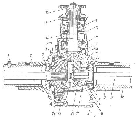
Figure 2
Adjustment of the differential bearings UAZ-469, UAZ-31512, 31514 is carried out by selecting the thickness of the packages of shims installed between the ends of the inner rings of the bearings and the satellite box as follows:
Press the inner rings of the bearings onto the necks of the assembled differential so that there is a gap of 3-3.5 mm between the ends of the satellite box and the ends of the inner rings of the bearings, then press the outer rings of the differential bearings into the cover and the axle housing, install the UAZ-469, UAZ-31512 differential , 31514 assembly into the crankcase, install the gasket and cover, screw the ganks onto the studs and, turning
differential through the hole in the neck of the crankcase, so that the rollers take the correct position, evenly tighten the nuts on the studs of the cover with the crankcase;
Unscrew the nuts, carefully remove the cover and gasket, remove the differential from the crankcase and measure the gap between the ends of the satellite box and the inner bearing rings on both sides of the satellite box with a feeler gauge, then select a package of gaskets equal to the sum of the measured gaps, and add a gasket with a thickness of 0 to this package .1 mm;
Remove the inner bearing rings from the pinion box, divide the selected gasket package in half and install it on the pinion box necks, read the deviation of the mounting distance M on the rim of the driven gear (see Fig. 2).
If the deviation has a negative value, then it is necessary to shift from the right package to the left package the gaskets, the thickness of which is equal to the deviation value. If the deviation value is positive, shift the gaskets from the left package to the right one.
The position of the drive gear of the axle reducer UAZ-469, UAZ-31512, 31514 is adjusted by selecting the required thickness of the ring 12 as follows:
Press the outer rings of bearings 9 and 11 into the axle housing, insert the inner rings with rollers and under an axial load of 10-12 kgf into the outer rings of the bearings, turning the bearings until the rollers are in the correct position, measure the size from the axis of the driven gear to the stop end of the inner ring bearing 11 and, according to this size, select such an adjusting ring that would provide the mounting distance of the drive gear equal to 83.485 mm.
The bearings of the drive gear of the main gear of the axle reducer UAZ-469, UAZ-31512, 31514 are adjusted by selecting such an adjusting ring 10 so that when tightening the nut 8 with a torque of 17-21 kg / cm, the moment of resistance to turning the drive gear with the oil seal installed is within 10- 20 kg/cm for new bearings and 4-10 kg/cm for run-in bearings.
If this cannot be obtained with one adjusting ring, shims can be installed. The measurement of the moment of resistance to turning the drive gear is carried out with continuous rotation of the gear in one direction and after at least 10 revolutions of rolling.
When checking with a spring dynamometer fixed to a hole in the flange, the dynamometer at the time of turning the gear should show a force of 2.5-5.0 for new and 1-2.5 kgf for run-in bearings. It is not allowed to unscrew the flange fastening nut in order to match the pin hole with the slot of the nut.
After adjusting the drive gear bearings, finally check the position of the driven and drive gears along the contact patch. The side clearance between the teeth of the driving and driven gears should be 0.2-0.45 mm. Measurement should be made on the drive gear flange at a radius of 40 mm (check in four positions of the drive gear every turn).
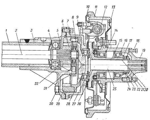
Figure 3
The assembly of wheel gears UAZ-469, UAZ-31512, 31514 is carried out in the reverse order of disassembly. In doing so, the following must be taken into account.
At the front wheel reduction gear of the axle, after tightening, unscrew the nut 19 (see Fig. 1) into the groove at the end of the shaft;
After tightening the bolts, bend the edges of the lock washers on the bolts of the bearing housing and the bolts of the driven gear to the edges of the bolt heads, and nuts 28 (see Fig. 1) of the fastening of the bearings of the driven shafts and nuts 27 (see Fig. 3) after tightening, open shaft grooves.
Assembly of CV joints of UAZ-469, UAZ-31512, 31514
After selecting new oversized repair balls or replacing one of the fists, assemble the CV joint UAZ-469, UAZ-31512, 31514 in the following order:
Clamp the long fist in a vertical position in a vice and insert the central ball, and then install the short fist on the central ball so that the marks marked with paint coincide and, turning it from side to side, install three peripheral balls in turn;
Spreading the fists by 10-12 mm and turning the short fist at the maximum angle away from the free grooves, install the fourth ball so that it bites into the grooves, and then turn the short fist to a vertical position. In this case, blows with a copper hammer on the rod of a short fist are allowed.
The preload in the balls of the CV joint UAZ-469, UAZ-31512, 31514 should be such that the moment required to turn the fist 10-15 ° in all directions from the vertical with the other fist clamped in a vise would be 300-600 kg / cm. The difference in the moments of rotation of the fist in two mutually perpendicular directions of one hinge must not exceed 100 kg/cm. The diameter of the central ball is 26.988-0.05 mm.
Each hinge must be assembled with balls of one group or two neighboring groups. In this case, balls of the same size must be placed diametrically opposite to one another. The difference in the diameters of two pairs of balls of one hinge is allowed no more than 0.04 mm. After assembling, run the hinge on the test bench while changing the angle from 0 to 30° for 2 minutes at 300 rpm.
When running in, lubricate balls and grooves with grease according to the lubrication chart. When assembling the drive of the driven drive wheels of the UAZ-469 and UAZ-469B front axles, the following must be taken into account. The sleeve must be pressed into the stub axle of the UAZ-469 car from the outer end of the trunnion to a depth of 18 mm, and into the trunnion of the UAZ-469B car - from the side of the trunnion flange flush with the end face of the socket under the thrust washer.
After pressing in, unfold the sleeve and iron it with a brooch to a size of 0 32 + 0.017 mm. The oil grooves of the thrust washers must face the pivot. To fix the washer in the socket, it is allowed to punch it in three or four points evenly spaced around the circumference.
When replacing the bushings of the pivots in the ball joint, the bushings after pressing must be machined for a pass. When installing the hinge, apply grease to the ball joint according to the lubrication chart, and lubricate the pivots and pivot bushings with liquid grease before assembly.
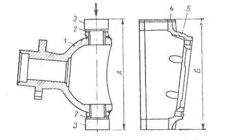
Figure 4. Selection of shims UAZ-469, UAZ-31512, 31514
M - ball bearing; 2 - support washers; 3 - pivots; 4- adjusting shims; 5 - body
The required number of gaskets to obtain certain axial interference in thrust bearings is selected depending on size A (Fig. 4) and size B. The number of gaskets must be at least five.
Dimensions are measured under a load of 160 kgf applied from above. Size A should be 0.02-0.10 mm smaller than size B. Install shims from above and below on the ends of the housing. With an even number of gaskets of the same thickness, put the latter on top and bottom in equal quantities.
With an even number of gaskets, but their different thicknesses, or with an odd number of gaskets, the difference between the total thicknesses of the upper and lower gaskets should not exceed 0.1 mm. When assembling and installing the stub axle oil seal, soak the felt ring in warm engine oil.
______________________________________________________________________________
UAZ cars cannot be called a very common group of vehicles on modern roads, but despite this, people are often interested in issues related to the design features of the front or rear axle or troubleshooting other components and systems of these vehicles. Given this fact, in this article we will consider the device of the UAZ front axle using the model 3741 as an example, or, as it is also called, “loaves”.
How the UAZ front axle works
The front axles of the old model, which include part of the UAZ-3741 design, do not differ much from similar new elements of the Spicer type. The fundamental differences between them lie only in crankcase design, dimensions of the components of the final drive and differential, as well as in some of the parts used.
The main part of the old bridge is a split crankcase, which consists of two divided halves, each of which has casings pressed into them with axle shafts inside. The casings also provide for the presence of safety valves, which are responsible for limiting the growth of oil pressure in the system.
 Located in the crankcase main gear and differential, which have a standard device: a drive gear with a small diameter is located in the horizontal direction and is connected to the universal joint. It engages with a large driven gear, which is located in the longitudinal direction. A differential is placed inside the driven gear, consisting of four satellites located on two axles, and two axle gears.
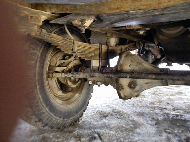
Along the edges of the crankcase there are pivot assemblies, which include ball bearings with housings of pivot pins (or steering knuckles) on them. On the side opposite from the axle shaft, the trunnions themselves are attached to the trunnion bodies, in which the wheel hub is mounted by means of two bearings. In the housings of the ball bearings there are constant velocity joints (CV joints), the outer pins of which are located in the hubs.
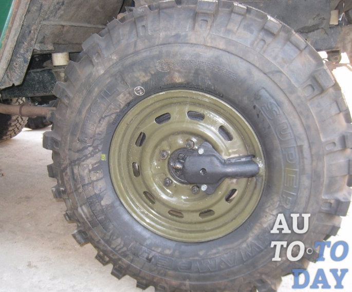
The main feature of the UAZ front axles is the presence in them of a mechanism for connecting the wheel hub with the axle shaft, which is made in the form of a coupling, with which you can connect or disconnect the hub and the hinge pin. This is what guarantees the transmission of torque from the differential to the wheel.
When the clutch is disengaged, the wheel hub can rotate freely on the trunnion, which means that the car will have a 4 × 2 wheel formula. When the clutch is engaged, the wheel hub through the CV joint will be connected to the axle shaft and differential, and the car becomes all-wheel drive - 4 × 4. The front axles of the old UAZ representatives, the design features of which are also characteristic of "loaves", were equipped with hubs with drum brakes installed on them. To control the wheelbase on the bridge, there are steering knuckle levers (located at the top of the steering knuckle housings) and steering rods connected to them.
Note! In the new bridges of the Spicer type, the steering angle of the wheels reaches 32 °, while the same indicator of older specimens does not exceed 29 °. Otherwise, driving with different types bridges are no different.
Possible bridge malfunctions and their causes
 The main malfunctions of the front axle include the formation of leaks of lubricating fluids, excessive wear of fasteners, defects in bearings, axle teeth, as well as mechanical damage to the beam and wear of components. The causes of these malfunctions can be very diverse. For example, if on a rear-wheel drive car, front-wheel drive, then driving on rough sections of the road will cause damage to the components of the transmission. The use of winter gear oil in summer period or flight fluid in winter, which is not the most in the best way affect the performance of the vehicle. Also, remember to keep your tires at a constant pressure to help prevent bearing and shaft problems.
As for the most common cause of various malfunctions of the UAZ 3741 front axle, in most cases, the basis for their appearance is a violation of the axial clearance of the pivots. To check whether it is broken or not, it is enough to raise the front of the car with a jack and try to shake the wheel up and down. If axial play is observed, then the pivot clearance will have to be adjusted. Interesting fact! The first car produced by the Ulyanovsk Automobile Plant, known as the GAZ-69, already had a 4 × 4 wheel arrangement, which provided it with simply phenomenal cross-country ability. Moreover, this vehicle was not whimsical in terms of maintenance, which was also an indisputable advantage. A similar concept of a "people's SUV", which was successfully implemented in the GAZ-69, still retains its relevance and continues to be implemented in modern models of the UAZ group.
How to remove the front axle
Given that the UAZ-3741 has a frame structure, then dismantling the front axle will not be particularly difficult. To complete the task, you will need durable and high-quality jack, stops, which can withstand one and a half tons, and a special liquid WD-40, to loosen rusty nuts. 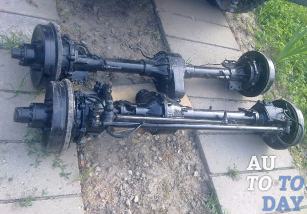 The procedure for removing the front axle is as follows:
- Chock the rear wheels to make sure the vehicle is secure.
- Disconnect the right and left brake pipes from the rubber hoses directed to the brake drums of the front wheels.
- Unscrew the nuts securing the brake hoses and dismantle the hoses themselves.
- Unscrew the fastening nuts of the lower ends of the shock absorber and the bolts connecting the cardan shaft to the drive gear flange.
- Loosen and unscrew the bipod ball stud nut and disconnect the rod from it.
- Now you should unscrew the fasteners (nuts) of the front spring ladder and remove the part (ladder) along with gaskets and linings.
- On last step work, lift the front of the car by the frame and remove the bridge from under it.
How to disassemble the bridge
When repairing the front axle, it must first be installed on a special stand. This will greatly facilitate the task of disassembly, which consists of several successive steps:
 Everything, on this dismantling of the UAZ bridge can be considered completed.
Did you know? The Ulyanovsk Automobile Plant, which is still producing UAZ vehicles, was founded in July 1941 and is part of the Sollers holding.
Dismantling the steering knuckle without removing the bridge
If you do not want to dismantle the front axle of the UAZ, but it is still somehow necessary to disassemble the steering knuckle, then you should follow these steps:
 Thus, by performing these simple manipulations, you can disassemble the steering knuckle without any need to remove the bridge.
Domestic off-road cannot scare UAZ car owners, but for their proper operation, it is necessary to adhere to certain operating rules.
So, for example, UAZ ("loaf") has a front axle, the device of which imposes certain requirements on the control of the machine. Among other things, such axles provide for disabling wheel hubs and axle shafts, which helps to increase the resource of axle parts when the front drive is turned off. Therefore, to turn on the UAZ-3741 front drive, you will have to perform two actions: by turning the clutch, connect the wheel hub to the axle shaft, and then, using the lever, turn on the front drive.
 In order not to damage the components of the structure, you can turn on the front-wheel drive only after the clutches are turned on, moreover, both on a non-working car, and in the process of its movement at a speed of no more than 40 km / h. If the drive enable lever with the car turned off does not want to occupy the working position, then you need to start the engine and switch it on the go.
As soon as the machine overcomes the problematic section of the path, perform all the steps in reverse order: stop the vehicle, turn off the front axle using the lever and turn the clutch caps to the “4 × 2” position. After that, the car will be able to continue its movement as a normal rear-wheel drive vehicle.
Remember! It is impossible to activate the front-wheel drive by means of a lever (from the passenger compartment) without engaging the clutches. Also, experts do not advise constantly driving with the clutches on, as this seriously reduces the life of the front axle and rubber.
Nevertheless, in the off-season and with the constant use of the UAZ-3741 in off-road conditions, the clutches can not be turned off, it is enough to adhere to a moderate speed limit.
Interesting fact! Nowadays, there are systems for remote rotation of clutches, which can have a pneumatic or electric drive. Engaging and disengaging clutches in the presence of such a system is performed by pressing a button located in the passenger compartment.
 As for the maintenance of the "loaf", it is not particularly difficult. Regularly check all sealing elements, clean the valves and, if necessary, tighten the existing threaded connections. In addition, do not forget about the need to periodically check and adjust the wheel bearings and diagnose the axial clearance of the drive gear.
Of particular note is the flooded into the bridge transmission oil, which should be replaced in a timely manner (according to the manufacturer's recommendations - every 40,000 km or more often, depending on the specific operating conditions, the age of the vehicle and the quality of the lubricant being filled). It is also necessary to perform periodic oil changes in the CV joint, wheel hubs and steering knuckles, and in the Spicer-type drive axles, the guide bushings of the disc brakes are additionally lubricated.
Regular maintenance and proper operation of the front and rear axles UAZ-3741 is the key to reliable operation of the car for many years.
Subscribe to our feeds
classic model
UAZ 3741 - all-wheel drive domestic passenger car, in Soviet time produced under the index UAZ 452. For the characteristic shape of the body, he received the popular nickname "loaf". In the factory configuration, it has an all-metal body, spring suspension and 2 drive axles with non-locking differentials that transmit power to all 4 wheels.
Rear-wheel drive is permanent, front-wheel drive is pluggable. Bridges are unified with UAZ 31512. Load capacity - 850 kg. Clearance - 220 mm. Repair of the UAZ 3741 front axle is extremely rarely required, since its design is quite reliable. Basically, it all comes down to replacing the wheel bearings and oil in the differential, ball and kingpins. But sometimes it is necessary to remove the bridge. And you have to do it yourself, since UAZ service centers are far from being everywhere.
We remove the faulty unit
Since the UAZ 3741 has a frame structure, it is quite easy to remove the front axle. To do this, you need to stock up on a powerful jack, stops that can withstand 1.5 tons of the weight of the front of the car, and a special liquid for unscrewing the nuts - WD-40.
The procedure is as follows.
- First you need to substitute the stops under the rear wheels.
- Then you need to disconnect the right and left brake pipes from the rubber hoses going to the front wheel brake drums.
- After that, unscrew the nuts securing the brake hoses and remove the hoses themselves.
- Next, you need to unscrew the nuts that secure the lower ends of the shock absorbers.
- After that, it is necessary to unscrew the bolts connecting the front cardan to the drive gear flange.
- Then you should unpin and unscrew the nut of the bipod ball pin.
- Next, you need to disconnect the traction from the bipod.
- Now you need to unscrew the nuts securing the stepladders of the front springs, remove the stepladders together with the linings and linings.
- At the end, raise the front of the car by the frame and pull the axle out from under the car.
After the old bridge is removed, you can proceed with the installation of a new part, following the steps in reverse order. If necessary, the removed unit is disassembled, troubleshooting is carried out, damaged parts are replaced and the bridge is reinstalled.
Correction of wheel axial play
The most common reason inappropriate behavior UAZ 3741 on the road is a violation of the axial clearance of the pivots. It is very easy to check whether it is broken or not - just raise the front end with a jack and try to shake the wheel up and down. If end play exists, the pivot clearance must be adjusted.
Adjustment is carried out as follows.
- We raise the front of the car, after putting the car on the handbrake.
- We dismantle the wheel.
- We unscrew the bolts securing the ball seal.
- We check the axial play by shaking the structure up and down with our hands.
- We unscrew a few bolts securing the upper lining of the kingpin. We remove the cover.
- We take out the thinnest shim and put the pad back.
- We perform the same procedures with the lower kingpin pad.
- We tighten all the bolts and check the result. If the backlash is eliminated, we fasten the oil seal and wheel back - and we go. If the play remains, we adjust everything again, this time removing thicker gaskets.
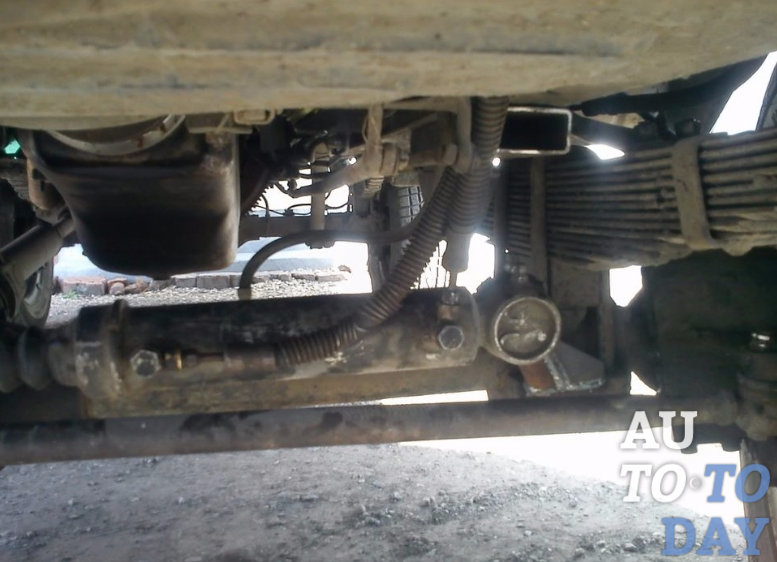
Here is the node on the car
It is important to pull out equally thick gaskets both from above and below in order to maintain the alignment of the CV joint. If the alignment is broken, after a while you will have to make expensive repairs.