Lovato 4 generation wiring diagram
Often after installation of the 4th generation gas equipment the owner of the car comes to the conclusion that it is desirable to make fuel consumption less. And the dynamic characteristics do not interfere with correcting. Someone goes to the workshop. But with proper skill and the availability of equipment, everything can be done by hand.
HBO adjustment
There is an opinion that it is enough to perform auto-tuning so that everything works clearly and quickly. This is mistake. Auto-tuning is the bare minimum of features that provide exceptional travel capability. For a comfortable and economical ride, it must be done manually.
To set up HBO, you will need the following tools:
- setup program;
- cable to the control unit;
- diagnostic cable.
But first, let's figure out what auto-calibration is.
Autocalibration HBO 4th generation
This is the first thing that is done after installing HBO. This program memorizes the petrol injection time. When switching to gas fuel, it correlates fuel carat coefficients with previously obtained data.
This setting does not apply to all revolutions and does not provide control of the entire load. The main goal is to create conditions for minimal movement.
HBO is configured in 2 versions:
- by load;
- fuel trim.
HBO adjustment according to load
Motor load is an indicator that indicates high level voltage that is proportional to the injection time. That is why the adjustment is performed by correcting the fuel injection period.
Here you need an adapter for HBO.
Step 1 - fix the petrol injection time.
Step 2 - transfer the car to gas fuel and fix the change in indicators.
During these actions, it is necessary to maintain the same pressure on the pedal. If the injection time on gas fuel has increased compared to the injection time on gasoline, then the mixture is leaner than necessary. Now you need to change the minimum injection value by adding the number of divisions equal to the difference between both indicators.
Manifold vacuum adjustment
The previous generation version cannot be used with a vehicle in motion. If desired, you can use another method that provides for synchronization with the readings of the MAP sensor, which records the vacuum in the collector.
Initially, the indicators obtained from driving on gasoline (at least 100 km.) are recorded. The values of vacuum in the collector are fixed. Then they pass the same distance on gas, also fixing the readings, comparing them with the MAP data and correcting them. For greater convenience, a spreadsheet is used.
HBO adjustment for fuel correction
Fuel injection tuning is the best way to adjust LPG. By comparing the fuel map data, stabilization of the values \u200b\u200band their stability under loads and revolutions is achieved. The maximum allowable fluctuations of indicators - +/-5%.
The electronic control unit, fixing changes in fuel, demonstrates indicators of deviation from the norm. Often, MAF and MAP sensors are compared, as well as tables of values. If the fuel injection is within normal limits, the readings will be 0.
The standard procedure for setting up the 4th generation HBO provides for adjustment by load, and then by the difference in performance. Often, the first one is enough for the stable operation of the system.
Installation of gas-balloon equipment on a car - effective remedy to reduce fuel consumption and extend the life of the machine mechanisms.
For uninterrupted and reliable operation of the system, timely adjustment of HBO 4 is required. This allows you to maintain the dynamic characteristics of the vehicle and keep fuel consumption at a minimum level. Without proper debugging of the system, engine errors and valve burnout may occur.
The best and fastest way to solve the problem is to contact the company "Vist-Electric". Adjustment of HBO of the 4th generation is carried out as quickly as possible with the use of accurate modern equipment.
Methods for debugging gas equipment
During the debugging of the equipment, the main task is solved - compliance with the time indicators of fuel injection. To configure HBO 4 generations, the following methods are used:
- according to the results of fuel correction. The most effective way, since the injection of the fuel mixture is directly adjusted. To set the most accurate indicators, an electronic control unit is used. With its help, the task of how to set up HBO 4 generations is quickly solved;
Initially, the map is regulated by loads, and the check by revolutions acts as a control measure. Measurement data is displayed as a percentage. The setting allows you to set fuel card coefficients within acceptable limits. The debugging process is carried out at various loads and engine speeds. In the final settings, percentages should not exceed +/- 5;
- application for setting up HBO 4 generations of the load stand. The car is placed on a special stand that simulates driving on the highway. With the help of electronic equipment, indicators are taken. At the end of the measurements, a comparative graph is displayed, which serves as the basis for making changes to the operation of gas-balloon equipment;
- automatic calibration. To adjust the 4th generation HBO, a control unit is used. He first fixes the time indicators of gasoline injection, then the device switches to gas fuel. As a result, the coefficient of the fuel map is corrected, i.e. the gas supply time begins to coincide with the petrol supply time. This setting is basic and allows the vehicle to operate in two fuel modes.
How to set up HBO 4 generations on the move
A common way to bring the system to an optimal state is to adjust it on the track. In this case, it is possible to provide the necessary temperature conditions for the operation of the engine and it becomes possible to maintain various loads at different speeds.

The tuning accuracy is achieved by carrying out the operation in real operating conditions and the possibility of repeated repetition of loads.
The results of the adjustment of HBO 4 by the company "Vist-Electric":
- setting minimum fuel consumption parameters;
- compliance with the optimal parameters of the engine;
- exclusion of the possibility of premature wear or failure of gas-cylinder equipment.
Adjustment of HBO 4 in the company is a guarantee of debugging the system in accordance with all technical and operational characteristics and safety standards.
Before installing gas equipment, disconnect the battery ground wire (unless it is prohibited in the car manufacturer's instructions).
ATTENTION: this erases the memory of the radio and phone, and work central locking and anti-theft system. In this case, you can temporarily connect the battery.
After drilling, be sure to remove burrs and carry out anti-corrosion processing of the edges.
Seal all wires passing through openings to prevent water from entering.
Install the control unit as far as possible from places where water can enter, sources of heat (eg exhaust manifolds), high voltage wires and where possible, install the unit with the connector down.
If a fuse blows, do not replace it with a stronger one.
Do not attempt to open the control box as this may cause damage beyond repair. LOVATO disclaims any liability for personal injury and property damage if LOVATO equipment shows signs of tampering. In this case, the warranty also ceases to be valid.
Make all connections using special connectors or solder them with soft solder.
Always comply with relevant laws and regulations for the installation of gas appliances.
Make sure the fuses are removed before installing the control box.
ATTENTION!
If these instructions are not followed, the system will not work or will not work properly. This may result in damage to LOVATO equipment and void the warranty.
INDICATIVE JET DIAMETERS FOR LOVATO EASY-FAST
The volume of one cylinder - D jet
0.35-0.4 - 1.6mm
0.4-0.45 - 1.8mm
0.45-0.5 - 2.0mm
0.5-0.55 - 2.2mm
55-0.6 - 2.4mm
0.6-0.65 - 2.6mm
0.65-0.7 - 2.8mm
For 16 valves + 10%
For turbocharged cars +30%
For pair-parallel -20%
For parallel -30%
GASOLINE INJECTOR HARNESS
There are different types of harnesses for connecting petrol injectors and gas control unit.
CODE DESCRIPTION NOTES 1080011 Harness EMU EASY FAST 4 universal Harness to disable injectors (4 cylinders without connectors) 1080014 Harness EMU EASY FAST 3 injectors BOSCH Harness to disable injectors (4 cylinders, JAPAN connectors, right) 1080015 Harness EMU EASY FAST Harness to disable injectors (4 cylinders, 1 connector) Fiat Stilo, Fiat Dobio-1.6, Peugeout-1.4, Citroen C3-1.6.1080016 EMU EASY FAST 3 Harness (BOSCH injectors, reverse) Harness for injector deactivation (3 cylinders, BOSCH type connectors, left)1080017 EMU EASY FAST harness 4 BOSCH injectors, return Harness for injector deactivation (4 cylinders, BOSCH connectors, left) 1080018 Harness EMU EASY FAST 4 injectors JAPAN, return Harness for shutting off injectors (4 cylinders, JAPAN connectors, left)
To select a harness, you must determine the type of connector installed on the vehicle and its polarity.
To determine the polarity, you must:
1. Disconnect one of the original injector connectors
2. Prepare a tester for measuring DC voltage with a range of up to 20 V and connect the negative contact to ground.
3. Attach a positive contact to one of the pins of the injector connector.
4. Turn on the ignition and check the voltage value with a tester. If the value is about 12 V - the cable is positive.
ATTENTION!
The power supply of the injectors has a time limit. A few seconds after the ignition is turned on, it may turn off. It is recommended to check the polarity of all injectors, as on some vehicles one injector has reversed polarity.
After defining physical form and the polarity of the injectors, you can select the appropriate harness.
Use harnesses 1080012, 1080013 and 1080014 if the injector positive wire is on pin 1 and the negative wire is on pin 2 of the original connector. If there are no numbers on the original connector, see the picture.

Use harnesses 1080016, 1080017 and 1080018 if the positive injector wire is on pin 2 and the negative pin 1 of the original connector. If there are no numbers on the original connector, see the picture.
If the original connectors are not compatible with the harness connectors, or if it is expected that installing a harness with connectors will be difficult, use harness 1080011. In any case, check the polarity of the injectors. You need to open the negative wires.
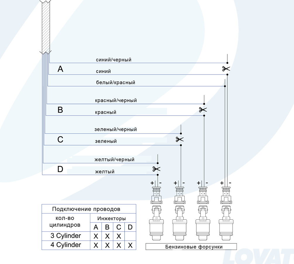
CONNECTING THE UNIVERSAL INJECTOR HARNESS TO THE VEHICLE'S ORIGINAL WIRING
Cut the wires from the petrol injectors. The single-color wire of the universal harness must be connected to the injectors, and the corresponding wires with a black stripe must be connected to the petrol injection control unit. Do not mismatch between injector emulator wiring and gas injectors. When connecting the gas injector “A”, the connection of the wires “A” of the injector emulator harness must match.
The same applies to other nozzles.
In 3-cylinder vehicles, the YELLOW and YELLOW-BLACK wires are not connected.


SWITCH OPERATION
The supplied switch has a button, 7 LED indicators and a built-in buzzer.

RED LIGHT - reserve
GREEN LEDs - gas level
CENTER BUTTON - switching fuel types
YELLOW LIGHT LIGHT - the car runs on gasoline
G-GREEN DIODE - car running on gas + system diagnostics
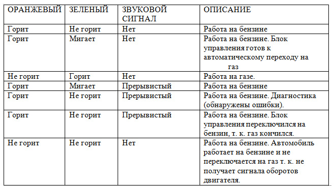
FUNCTIONS OF THE LED INDICATORS
SWITCHING TO PETROL DUE TO LOW GAS PRESSURE
When the switch reaches the reserve and when the gas pressure drops below the set value, the control unit automatically switches to gasoline. This is to avoid running too lean and causing damage from this catalyst. Refuel the vehicle before switching to gas. When switching to petrol, LOW GAS PRESSURE causes the switch LED to turn ON ORANGE (Petrol operation), RED and four GREEN LEDs flash alternately, and an intermittent horn sounds. To return the switch to normal operation, the BUTTON must be pressed once, the ORANGE LED remains on, indicating that the vehicle is running on gasoline, the audible signal is turned off.
EMERGENCIES
If the car does not start on petrol (due to problems with the fuel pump, etc.), you can start the car ON GAS. To do this, start the car while holding the button down.
ATTENTION!
Starting on gas is considered an abnormal situation. Constant starting on gas can damage the catalytic converter and cause the Check Engine signal to turn on. The system allows 5 starts on gas!
DIAGNOSTICS
When diagnostic errors are detected, the ORANGE LED ILLUMINATES (petrol operation), the GREEN LED FLASHES and an intermittent audible signal sounds (the gauge LEDs are OFF). To disable sound signal you need to press the switch button.
SOFTWAREEASYFAST
MINIMUM SYSTEM REQUIREMENTS
Operating system - Windows 98 2nd edition or later
Memory (RAM) - min 16 MB
Hard disk - at least 20 MB
Monitor resolution - 800×600 or higher
INSTALLING THE SOFTWARE
To install the program, insert the disc into the drive and wait for the
installation instructions.
If the program does not start, click "Start" / "Run" and type "D:
Exe" (D stands for CD-Rom)
You will be prompted to select a folder to install. We suggest that you do not change the default address.
During installation, a shortcut is automatically created on the desktop.
INTRODUCTION
The calibration program works with hardware key code 7155002 and can
work without connection to the control unit.
To connect the control unit, it is necessary that the control unit and the computer are properly connected with a serial cable (Code 0570001) and a serial USB adapter if the computer does not have a serial port (Code 4685001 serial USB adapter).
MAIN MENU
Select the language to use the program. Further from this menu, you can access all the submenus of the program, which are described individually below.

The bottom of the menu contains the following information:
1. Shows if the control unit is connected to the program. It is important to remember that all settings and adjustments made without connecting to the control unit will be lost when connected, unless they are first saved in the configuration file. When launched, the program automatically tries to connect to the control unit. If there is no connection, an error message appears. In this case check:
Serial interface connection
Connecting the control unit to the battery and ground
By clicking on shortcut 1, you can establish (Ctrl + C) or disconnect (Ctrl + D) the connection
2. Software version
3. Firmware version of the control unit. To update, enter the submenu
"New firmware" and select the desired version from the list.
NOTE: This operation is only available with Internet Explorer version 5.5 or later.
4. Vehicle configuration name. If a previously saved configuration is loaded into the control unit, its name will appear. If the control unit is new, the message "Standart Lovato" will appear, followed by "LPG".
5. Exit the program.
VEHICLE CONFIGURATION
This menu consists of four screens in which you can set parameters that are responsible for the operation of the gas control unit. At the top of all screens, the current values of the system's general operational alarms are displayed.

1. Shows whether the car is running on gasoline or gas, as well as a gas level indicator, moreover, the button allows you to switch using the program.
2. Shows:
Turnovers ("REVS») – Engine speed measured in real time by the gas control unit.
T gas– Readings of the temperature sensor located in the filter.
T reducer– Reducer temperature, readings of the temperature sensor located in the reducer.
3. Shows:
Gas pressure ("GASPRE») – This is the difference in gas pressure in the gas injectors and in the intake manifold, measured by a pressure sensor installed in the filter.
IDA– Vacuum in the manifold, determined by the sensor located in the filter.
4. Shows:
Gas injection time "Gas time" ("GAStime”) and gasoline “Gasoline time” (“PETRtime») . One or two values can be obtained for each variable, depending on the number of cylinder banks set in the Number of cylinder banks pop-up menu in the Sensors window.
5. Shows:
Lambda probe voltage received through the WHITE and WHITE-BLACK wires. If the latter are not connected, "no data" ("n. d.") is displayed.
6. There are three warning lights here:
Additional injection– If the program detects an after-injection, the corresponding light will turn YELLOW and turn GREEN for 2/300ms, so that the operator can see the moment of the after-injection.
Cut-off– The corresponding lamp lights up RED in cut off mode (engine braking, petrol injectors closed).
Diagnostics - Lights up RED when an error is detected. When you click on "Diagnostics", a window appears with a description of the error.
CONFIGURATION
In this window, you can set the parameters of the car

ATTENTION!
Parameters marked BLUE must be modified with the ignition off.
FUEL TYPE ("fueltype»)
This selection is used to enable the control unit with the characteristic parameters previously set for correct operation on the type of fuel used. Choose:
LPG– for vehicles running on PROPANE
METHANE– for vehicles running on methane
Selecting PROPANE or METHANE also changes the folder where the configuration files are saved (see "Loading the configuration").
INJECTION TYPE (“Injectiontype»)
Allows you to select a gas injection strategy depending on the type of gasoline
Sequential (proposed option) - gasoline injectors are switched on one by one.
Full group ("Full group") - gasoline injectors are switched on simultaneously.
NOZZLE TYPE
Allows you to select the type of GAS nozzles included in the installation kit. When loading a previously saved configuration, this window shows the type of gas injectors provided in the configuration file. If the type of gas injectors previously stored in the control unit does not match the one displayed in the window, a warning message appears. To solve the problem, it is necessary to load a configuration file that determines the type of installed injectors or change the type of injectors set in the control unit. If the injectors installed on the vehicle do not match the selected ones, they are set to incorrect parameters, which may cause equipment malfunction or damage to the injectors. You can choose from Matrix or Lovato nozzles.
RPM SIGNAL TYPE(BLACK wire) ("Rew signal type")
Standard - select this option when the BLACK wire is connected to:
Revolution counter with square wave signal 0-12V.
The negative pole of the ignition coil.
Weak signal - select this option when the BLACK wire is connected to:
Revolution counter with 0-5V square wave signal.
Non-contact switching of square wave type 0-5V.
These signals can be determined using an oscilloscope.
TYPE OF REEL
This parameter is used by the control unit to correctly calculate the standard engine operation, which depends on the type of ignition to which the BLACK wire is connected. Choose:
Single bobbin - for cars with coils on each cylinder, if the BLACK wire is connected to the negative pole of one of the coils;
Double bobbin - for cars with a coil for two spark plugs, if the BLACK wire is connected to the negative pole of one of the coils;
Revolution counter - for vehicles with a coil and a mechanical distributor if the BLACK wire is connected to the negative pole of the coil or on all vehicles on which the BLACK wire is connected to the signal wire of the rev counter.
Rev counter 2 - for 6 and 8 cylinder vehicles where the BLACK wire is connected to the rev counter and engine RPM is not measured correctly.
NUMBER OF CYLINDERS
This parameter is used to set the control unit to the number of cylinders of the vehicle's engine and therefore the number of gas injectors it will control, select 3 CYLINDERS or 4 CYLINDERS according to the number of engine cylinders. When using the control unit on a vehicle with 5 - 6 - 8 cylinders, select 5 CYLINDERS, 6 CYLINDERS or 8 CYLINDERS according to the number of engine cylinders in the selection window.
ZERO (RESET)
Pressing the reset button cancels all settings of the control unit and loads the factory settings.
SWITCHING
This window allows switching from petrol to gas and vice versa.

SWITCHING»)
During Acceleration - Switching from PETROL to GAS occurs during acceleration when the engine speed exceeds the "SWITCH THRESHOLD".
The number of revolutions exceeds the "THRESHOLD NUMBER OF TURNS FOR SWITCHING" and then falls below this value.
At "Cut - Off", when the engine speed exceeds the "THRESHOLD RPM FOR SWITCHING".
THRESHOLD NUMBER OF REVOLUTIONS FOR SWITCHING("Rev threshold for switching")
Sets the engine speed at which the switchover from petrol to gas will occur.
REDUCER TEMPERATURE FOR CHANGING
Sets the value of the temperature of the reducer, after reaching which the switchover takes place. Until the set temperature is reached, the control unit DOES NOT SWITCH TO GAS. If the temperature drops below the set temperature during gas operation, the control unit always remains on gas.
We suggest setting the temperature between 20º and 40º because: If the temperature is set too low, the changeover will occur when the gearbox is not warm enough. When asked too high value, it will take too long before switching to GAS.
WARM SWITCH DELAY("Switching delay with engine warm")
Sets the minimum time from engine start to switch from PETROL to GAS. We suggest setting the time to at least 25 seconds to make sure the system is working properly.
ADVANCED INJECTION SEQUENCE
This procedure allows automatic injection sequence advance as well as gas injection phase shift; the amount of phase shift depends on the "Number of rows of cylinders" command on the Sensors F3 page.
This advance can improve engine performance, especially when the gas injectors are far from the intake manifold.
This function should only be used when absolutely necessary, as it disables the GRADUAL PETROL-GAS changeover and makes the changeover instantaneous.
IDLING ("Idleoperation»)
On gas - when this option is selected, the car always runs on gas (recommended and set by default).
Return to petrol - when returning to minimum speed, the control unit switches to petrol for a few seconds, and then back to gas, thus avoiding a stop of the engine. We recommend that you use this feature only when necessary. The value "Revolutions to determine the minimum" ("Giri per identificazione del minimo") determines the number of revolutions below which this procedure is used.
Gasoline - work on idling below a predetermined threshold all the time occurs on gasoline. Return to operation on gas occurs when the specified threshold is exceeded. This option is recommended when gas operation is not possible, unstable or causes frequent engine shutdowns. That the system is running on petrol is not displayed on the switch, which still indicates that the vehicle is running on gas, but this can be determined on the computer as the gas injection time is reset.
HIGH RPM WORK
When the gas injection time limits are reached (gas exceeds the cycle time), a small amount of gasoline is added at the same time as the gas. The switch indicates that the car is running on gas. If the box is unchecked, this function is disabled and when the gas injection time limit is exceeded, automatic switching to gasoline is performed and displayed on the switch.
SENSORS ("SENSOR»)
In this window, you can select the configuration of the level sensor and oxygen sensor.

NUMBERROWSCYLINDER("Number of banks")
Required to set the number of rows of cylinders into which the engine can be divided.
CORRECTOR OF THE SECOND ROW OF CYLINDERS("Second banks corrector")
This item will appear when the number of rows is set to 2. On vehicles with two front lambda probes, this allows you to modify (increase and decrease) the percentage of GAS mixing when the two rows are slightly unbalanced.
In more detail for a 4-cylinder engine, this means that the mixture formation of injectors B and C on the one hand and A and D on the other is unbalanced. 6- and 8-cylinder cars, the mixture formation of gas injectors connected with wires with a RED stripe is unbalanced with the rest of the gas injectors.
TYPE OF FRONT LAMBDA PROBE("Front lambda probe types")
With the correct setting of this parameter, the control unit can determine the operation of the lambda probe. Before determining the type of lambda probe, it is necessary to check their operation with a digital tester.
For sensors with voltage 0-1V, 0-5V, 5-0V, 0.8-1.6V, if you only want to read their readings, proceed as follows:
Connect the WHITE wire to the lambda probe without breaking the original connection (do not connect the YELLOW wire).
When using a lambda probe type UEGO, it is not possible to read the sensor voltage value (in this case, use an OBD scanner).
0-1V - select this option if the voltage on the signal wire varies within:
o about 0.8-1V with a rich mixture
0-5V - select this option if the voltage on the signal wire varies within:
o about 0-0.2V lean
o about 4.8-5V at a rich mixture
5-0V - select this option if the voltage on the signal wire varies within:
o about 4.8-5V lean
o about 0-0.2V with a rich mixture
0.8-1.6V - select this option if the voltage on the signal wire varies within:
o about 0.7-0.8V lean
o about 0.4-1.6V with a rich mixture
TYPES OF GAS LEVEL INDICATORS("Gas level indicator type")
Indicates to the gas control unit which type of level sensor is being used:

INCREASED GAS PIPE FILLING TIME("Gas pipe filling time")
Usually, the gas control unit, in order to prevent a possible engine stop when switching from one type of fuel to another, turns on the gas valves 5 seconds before switching: this ensures a better filling of the tube with gas.
You can disable this feature. In this case, the gas valves are only activated for approximately 1 second.
ATTENTION!
Never turn off the fuel pump.
In many cases, motorists may need to diagnose 4th generation HBO with their own hands. Gas equipment of the fourth generation is quite reliable. But only if it is configured correctly. Therefore, when installing such structural elements, be sure to carry out diagnostic work. This will help to set up the equipment as efficiently as possible.
Diagnostics may be required if any problems arise with the operation of the engine. The complexity of the situation lies in the fact that there are very few specialists in the services who can do this work efficiently. You will most likely have to do it yourself.
Setting
Do-it-yourself diagnostics of HBO 4 generations can be carried out with self installation equipment for the car. To do this, you will need a diagnostic scanner, or a laptop with the appropriate program.
With the help of such devices, the fuel correction of the ECU is determined. It is calculated as a percentage of normal fuel injection. Reference readings of monitoring sensors are taken as a basis. The equipment is configured in such a way that the correction occurs within + -5%. Tuning is best done under load. After the result is checked at idle. Usually no further configuration is required.
![]()
Faults
Another case in which diagnostics is required is breakdowns and malfunctions. In this case, very often diagnostics using a scanner does not help. Errors say only about a poor or rich mixture. But true reason do not disclose. In this case, part diagnostic work carry out manually.
Often the speed on the internal combustion engine (internal combustion engine) equipped with gas-balloon equipment begins to float. There are only two reasons for unstable work:
- No spark;
- No fuel.
Take a close look at the pressure. If it falls in the system at sharp increase rpm, the gearbox should be replaced. If there is a lack of antifreeze in the cooling system, the gearbox may overheat, which will also lead to unstable engine operation.

Sometimes . This is an unfortunate situation. First of all, you need to check the operation of the ignition system, the correct inflation of tires and other factors affecting fuel consumption. If everything is in order, we perform diagnostics of HBO.
First, we check the operation of the system using equipment. Perhaps it will turn out right away, to establish the cause of the malfunction. After that, they check in turn:
- . This is a common cause of increased fuel consumption;
- Adjustment of the gas reducer;
- Faulty injectors, they may need to be adjusted.

Other problems
Owners of vehicles with LPG equipment face other problems. Moreover, these difficulties can be connected with HBO only indirectly. Such malfunctions include the lack of automatic switching from gasoline to gas. In this case, you need to check the serviceability of the gas temperature sensor. It could also be due to low battery voltage. Another reason is the failure of the tachometer or a broken wire going from it to the HBO.
Severe dips when running on gas, up to engine shutdown, signal the need to check the ignition. Most often, the cause is high-voltage wires or spark plugs. The fact is that a more powerful spark is required to ignite the gas mixture, in comparison with gasoline. If it is not strong enough, then there will be problems with the use of HBO.
Conclusion. When operating gas-balloon equipment, the driver will sooner or later encounter problems. Most often, malfunctions and failures occur due to careless operation. In most cases, do-it-yourself HBO diagnostics of the 4th generation is more effective than a similar procedure in the service. Therefore, it is better, having carefully studied the device of this system, to find a malfunction on your own.
The dynamic parameters of the car and fuel consumption do not always suit car owners when installing gas-balloon equipment, since in many workshops experts believe that the automatic Italian system exhaustively solves tuning problems.
But, as practice shows, automatic adjustment consistently provides only one result - the car does not stall. The settings in the complex need to be carried out only manually, an indispensable device in this issue is HBO diagnostics. Proper adjustment is designed to ensure the same fuel injection time, regardless of whether the car is running on gasoline or gas. Solve this issue - the main problem for the car owner.
Two options for setting up HBO:
- Adjustment of gas-balloon equipment according to the load. In this case, you will need cable for HBO diagnostics. Adjustment is carried out according to changes in the spray time. In this case, it is better to use older versions of programs that have coarse adjustments.
- Setting HBO for fuel correction. This procedure is carried out using a diagnostic adapter for HBO 4th generation. Configuration can be done using any program. The programs are free. They are written by HBO manufacturers in order to install their equipment. So, you need an adapter and a program.
One clarification should be made, since most drivers find that the load on the engine increases with increasing speed. This is a completely misunderstanding of the issue. For example, in neutral gear, you completely squeeze the gas, while the speed increases to the maximum, but the load on the engine in this case is as low as possible. Thus, the load on the engine is directly proportional to the injection time, which is equivalent to rarefaction in the manifold, because more air is needed to burn a large amount of fuel. Therefore, the engine load is proportional to the rarefaction of the collector. Now consider what happens with each of the calibration options.
Automatic calibration
This option is considered by most installers of gas-balloon equipment to be quite sufficient. But on the other hand, it is with automatic calibration that you should start tuning. This is a fairly simple procedure. The control unit fixes the injection of gasoline. The ECU then switches to gas and corrects the fuel map coefficient. Thus, gas begins to duplicate the time of gasoline. But this option calibration has a significant drawback - it fixes only 1 cell and changes the map exactly according to it. For example, Lovato corrects the map according to idling, and OMVL - for minimum loads at 3 thousand revolutions. This is enough for the vehicle to move, and in motion it could be adjusted. That is, the adjustment of all loads at all speeds is not carried out.
Injection time adjustment
Setting up gas-balloon equipment implies adjusting the cells according to the time (t) of fuel injection, and not according to engine speed. Don't forget cord for HBO. That is, the moment of injection of gasoline fuel is fixed at a specific point in time, switch the car to gas, and see how the indicators change. The force of pressure on the pedal, as well as the circumstances of the movement, should not be changed. For example, the value was 3 ms, and now it is 4 ms. The increase is 33 units in percent. Accordingly, this is an indicator of the poverty of the mixture by 33%. The 3ms line changes to 33 divisions and the same must be done for the entire load of the engine. But this method will be absolutely unsuitable when setting up a car in motion, since it is extremely difficult to find a track with ideal coverage and fix your foot in the same position. It is more convenient to collect data and analyze indicators later.

Orientation to the vacuum in the collector
First, the indicators of movement on gasoline are recorded, then on gas, they must first be synchronized according to the values of the MAP sensor, which shows the vacuum in the manifold. Sequencing:
- To bring the fuel correction back to normal, for this you need to drive about 10 km on gasoline.
- Record and save data when driving on gasoline.
- Record the manifold vacuum values.
- Record and save data when driving on gas.
- Gas data adjusted according to MAP.
For ease of analysis, it is better to use a spreadsheet.
Fuel trim setting
The best option is to adjust the fuel injection, which performs diagnostics of HBO 4th generation. It shows the fuel correction by the electronic control unit, which displays the percentage deviation from the norm. As a rule, the indicators of MAF or MAP sensors and tables are considered and compared. normative values. If the fuel injections do not correspond to the set figures, then the indicators are non-zero. For example, a car runs on petrol with a value of 3ms and on gas with a value of 4ms. In this case, the correction will be 33%.
The meaning of the setting on the HBO adapter is to compare the coefficients of the fuel card in such a way that at various revolutions and loads used, they do not exceed the value of +/- 5 as a percentage. Initially, it is recommended to adjust the map according to loads, and only after that look at the difference in speed indicators. The second stage is usually the control one. RPM adjustment is usually sufficient.
The advantage of the adapter is that it allows you not to calculate the deviations in your mind, which allows you to configure in real time. That is, while the car is moving, you can observe the coefficient map and fuel correction values. There is also the opportunity to make changes and monitor the reaction of your vehicle. You can use an OBD adapter connected to a laptop. In this case, the information can be recorded and processed later by linking to the MAP sensor.