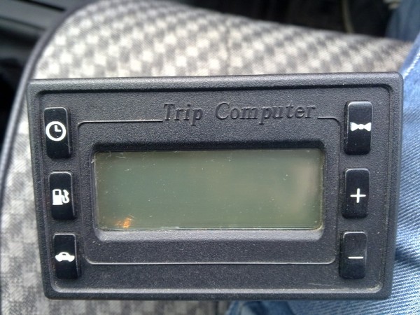
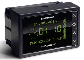
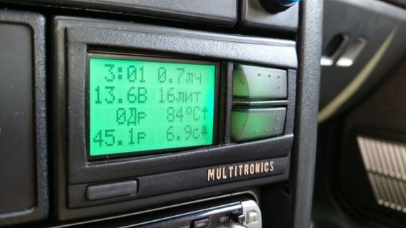
Vaz 2110 regular onboard. On-board computer "Trip Computer"
On-board computer the VAZ 2110 injector is necessary when there are problems in the operation of the car. It is with its help that you can quickly and easily determine what is the cause of the injector problems.
The on-board computer on the VAZ 2110 is a device that greatly facilitates driving a vehicle, but like any system it has its drawbacks and advantages, which will be discussed below.
Differences between an injector and a carburetor
In fact, the injector is practically no different from the carburetor. They have almost the same design.
However, if you assume that replacing the carburetor with an injector will not bring any benefit, then this is not so.
Consider the advantages of the injector:
- If there are any problems in the car, then it will be possible to find them in just a few minutes.
Note: nevertheless, you will have to go to a car service, where specialists will diagnose the condition of the car through.
- Even on idling the engine runs as it should. And in winter, you can start a car without problems, without preheating the engine.
- In general, the car drives much better. At the same time, it spends much less fuel when compared with a carburetor model.
- The carburetor should be cleaned and adjusted periodically, while the injector requires almost no intervention.
Note: Injector parts cost a little more than carburetor parts, but the injector breaks much less often. It is enough to follow the rules of operation of the car.

Usually a new injector (see) works long time. And even if it breaks down for some reason, it can be taken to a car dealership where repairs will be made free of charge, as it will be under warranty.
If a sensor is broken, then it can be replaced in a matter of seconds. And yes, these parts are cheap.
Disadvantages of the injector
The main disadvantages of the injector include:
- Catalyst, which is located at a distance of 0.1 m above the ground.
Note: therefore, you need to drive a car very carefully, as the catalyst can be easily damaged. This situation is especially possible when driving on rough roads. Besides, it costs a lot.
- Since the old model engine installed on the VAZ 2110 is not designed for an injector, it is very difficult to get to some of its parts.
How to drive a car with an injector
You can give a few important tips for the operation of a car with an injector:
- Maintenance needs to be done on time.
- Refuel the car only with the recommended fuel from the manufacturer.
- Soundproofing is necessary, as the injector works quite loudly.
- The body should be treated with anticorrosive.
Note: processing is necessary so that the body does not corrode.
Advantages of the on-board computer
The on-board computer of the injector is able to independently check the condition of the car.
Many install it on their car, because:
- It shows the correct one, so the driver can always know when he needs to fill up the car.
- There is a voltmeter and a tachometer.
- The oil change reminder function works.
Note: it costs no more than 2000 rubles, but it performs a lot of useful actions.
Problems reported by the computer:
- During the operation of the car, the following problems may occur: a light may come on, indicating a malfunction in the engine (but the computer is working normally).
Note: It is possible that this light comes on due to a small short circuit, so it is not advisable to drive to a car service every time it is on. Diagnostics is not cheap.
- The car is using too much fuel. Sometimes even more than the maximum limit of 12 liters can be spent per hundred.
In this case, only the firmware of the controller will help. This process is best entrusted only to highly qualified specialists, as it must be performed correctly.
Installation
Before starting the installation of the on-board computer, you should pay attention to the connection diagram.
Its installation takes place in several main stages:
- Remove the terminal coming from the battery.
- Find the block for turning on the alarm (see) and get it. It is to it that the on-board computer will be connected.
- Remove the orange wire from the seventh contact.
- In its place, fix the red and white wiring pulled out of the on-board computer harness.
- Disconnect the orange wire and install it in the connector from which the wire was previously removed.
- Disconnect the red wire with black stripes from the tenth contact. Install the red wire from the harness here. And in place of red, connect red-black. That is, the wires need to be swapped.
- Disconnect the black wire from the fifth contact. Connect the black wire from the harness to it.
- Connect the black wire of the block here.
- Remove the white wire from the eighth pin and connect the white wire from the harness to this connector. And vice versa.
Note: there must be contact between the wires.
- Now you should check if the wires are well fixed. The place of their twisting should be isolated with insulating tape.
- Through the inside of the console, the harness must be pulled to the installation site of the on-board computer.
- Connect it to the sensor that regulates the fuel level in the car.
- Remove the instrument panel, gaining access to the gray block.
- Disconnect the fuse box.
Note: it is mounted to the left of the driver.
- From the gray block, you need to pull out the pink wire, which gives a signal to the fuel sensor. You need to connect a pink bundled wire to it.
- Install on-board computer.
- Turn on the ignition and check how it works.
Our instructions will help you easily install the on-board computer on the car with your own hands. The approximate price of the on-board computer ranges from 2000 rubles.
For the work of a car mechanic, you will need to pay another 2,000 rubles. Therefore, you can save money by doing all the work yourself.
Before starting work, you should consider photos and videos on a given topic.
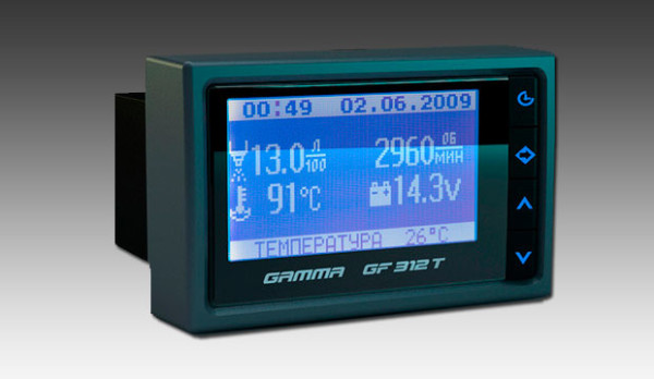
Once I had a need for an on-board computer for my "swallow" VAZ2110. The engine there is injection and is controlled by an incredibly smart Electronic Control Unit (ECU), which can tell a lot of things about itself and the engine, if asked correctly. Firstly, it is convenient to find out the reason for the Check Engine indicator on the dashboard to turn on (not that it often turns on, but still), and secondly, you can find out a bunch of interesting and useful engine parameters (the state of the same mass air flow sensor (DMRV)) .
Naturally, at first I visited the car market, with the idea that such a simple device simply had to be inexpensive. What was my surprise when I saw the prices. I don’t even know what the manufacturers stuffed there, but the prices did not fit into the adequate category. In this regard, I decided to make the device myself. Fortunately, the protocol for communicating with the ECU (Keyword Protocol 2000) is extremely simple and there is a complete description of it on the Internet. Data exchange is based on the request-response principle in asynchronous mode over one wire. This disgrace is called K-Line. It works very simply, we send some request in the form of a data packet, after which we receive a response in the form of another packet.
Initially, I wanted to assemble a circuit on an AVR microcontroller (hereinafter referred to as MK) Atmega16 or Atmega32 and a display from some ancient mobile phone with a resolution of 176x220 or so. But then I remembered that in ancient times, when the dollar was very cheap, I ordered this display:
Judging by the description, this is a color TFT display with a resolution of 320x240 and a diagonal of 3.2 ", it is controlled by the SSD1289 controller. In addition, a touch panel is installed on the display, which is served by an ADC installed on the board with the display and communicating with the MK via SPI. This miracle of Chinese technology cost in the region of 300 rubles and had only one small drawback - a parallel data bus for controlling the display controller... And these are 21 wires (16 - data bus and 5 - service). in terms of speed, it means you need something more powerful.As a result, I settled on STM32, quite cheap and powerful MK.After some time of searching, I found that STM32 controllers have a wonderful thing called FSMC (Flexible static memory controller).This is an interface for connection of external memory via a parallel data bus, while the MK will work with it as with its own internal memory, the address space expands to external memory. with and write the data. It is there that you can and even need to connect such a display and, as a result, get hardware support for working with a display on high speed. At the same time, without loading the controller itself, everything is hardware.
The choice fell on STM32F103VCT6. It is a 100-legged centipede in an LQFP package, contains an FSMC block, a DAC, a whole bunch of USART, SPI, etc., 256 KB of memory (at least program it), and has a core clock speed of 72 MHz (without problems, it can be increased to 120 MHz without loss of stability of the MC). Full description can be found in the datasheet attached to the article. Next, the structure of the device was thought out. It was immediately decided to make the interface based on graphic elements (in other words, pictures), then it was necessary to solve the problem of storing this very graphics. Because the display is large enough, and even at least 16 bits of information go to the output of each pixel (RGB565 mode), then there can be no talk of storing graphics in the MK's memory. Therefore, it was decided to connect an SD card and store all multimedia information on it. And here again a huge set of peripherals STM32 controllers came to the rescue. There is a special SDIO interface for the SD card, this is the "native" interface for SD and MicroSD memory cards (however, I found out about this later when I stepped on the first rake).
So the functionality is as follows:
- Obtaining from the ECU such parameters as: Mains voltage, Engine speed, Engine temperature, Fuel consumption (instantaneous, per 100 km), Movement speed, Position throttle valve, MAF voltage, Injection time, Mass air flow, Cycle air flow, Injection pulse duration, Regulator position idle move. Reading and clearing errors.
- Indication of serviceability of lamps and coolant level.
- Filter replacement reminder.
- Calculation of the distance traveled and fuel used.
- Control of headlights and marker lights.
- Measurement of temperature in the cabin and overboard with statistics.
- Time display.
- Interior lighting control.
- Sound and light notifications.
Also, the plans were to implement a USB diagnostic adapter as one of the functions, but so far there is not enough free time and USB on the STM32 has not yet been figured out.
Of course, bugs still occasionally slip through, but most of the functionality works fine, and bugs are gradually caught and fixed.
As soon as I decided on the hardware and functionality, I made a diagram and laid out the board. As it turned out later, the scheme was not well thought out (initially, the SD card was connected via SPI and it was sorely lacking in speed, and various minor flaws). As a result, there were both the second and third versions of the circuit, but in the end everything worked out, the iron works very stably both in the heat and in the cold. In the course of manufacturing and refinement, it was decided to divide the device into blocks: the main board with the MK, its harness and power supply, ULF, K-Line adapter and microSD and USB board.
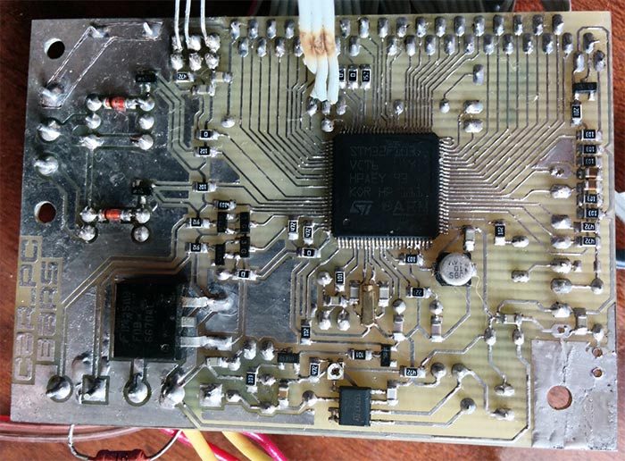


Let's consider the scheme of each of them in more detail. So, the board with MK:

Let's go left to right, top to bottom. The connector with the mysterious name D / S1 is designed to control the opening of doors and turn on the ignition. A board with a K-Line adapter and transistor switches is connected to the SENSORS and USART connectors to control the output of the lamp control relay, coolant level sensor and speed sensor. Next comes the P12 connector, the Photo pin is a photoresistor for lighting control, the second pin is connected to GND, SPEED is the speed sensor signal from the K-Line adapter board. The POWER connector supplies power to the circuit, and also removes voltage for interior lighting.
On the right side of the diagram are connectors for connecting peripherals. Connectors P2, P5, P9 and PEN_IRQ connect backlit display and touch panel ADC, micro SD card, and USB connector. With DS18b20 everything seems to be clear. SOUND connector for connecting ULF (sound notifications), K-Line_Pow - power supply for the board with an adapter, AMP_Pow - power supply for ULF (initially, the ULF power was removed completely, but it turned out that it was not possible to remove and supply power to the ULF best idea, it takes a few seconds to turn on, as a result, a ULF with the STDBY function was used, so now the MOSFET output is connected to the STDBY input of the ULF). Well, the LED connector for connecting the LED light notifications.
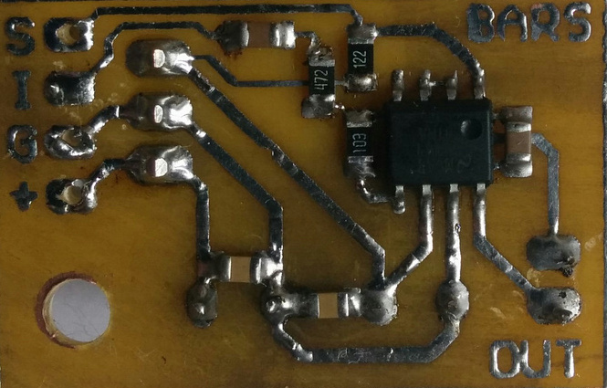
In the K-Line adapter circuit, everything is standard, the circuit is assembled on a comparator and is quite well known on the Internet:
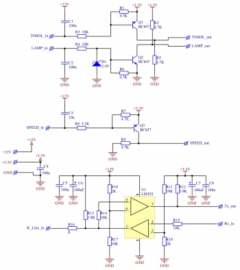
There is also a harness necessary to coordinate with the sensors.
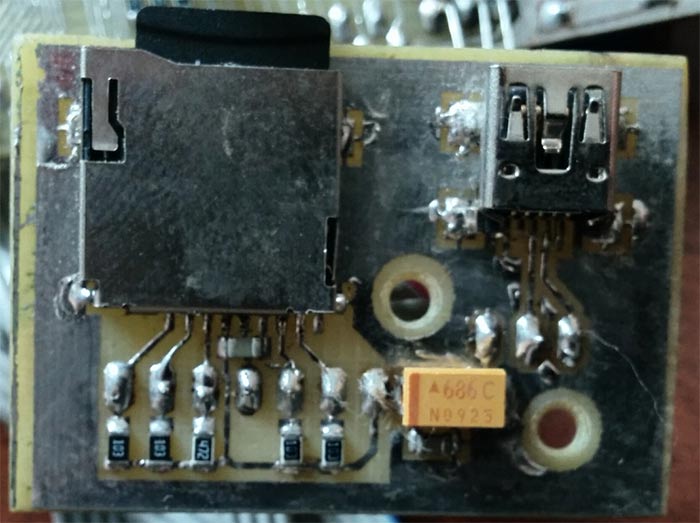
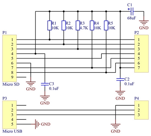
With an SD card, everything is just as simple, the standard strapping for SDIO:
Initially, the ULF was assembled on the TDA2003, but due to the lack of the STDBY function, it had to be abandoned and the ULF LM4991 ordered from Texas Instruments was used. This is a 3-watt ULF in a SO-8 package and 5V power supply. The diagram is taken from the datasheet:
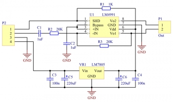
The ULF is on all the time, but so far no sounds are required to be played, it is in STDBY mode, as a result of which the consumption does not exceed 2 μA (typical according to the datasheet is 0.1 μA).
The board for the SD card is divorced in Sprint Layout, because. remained from one of the first versions of the scheme, and for all the rest in AltiumDesigner, because. I completely abandoned Sprint Layout.
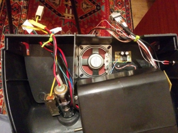
When assembled, everything looks like this:

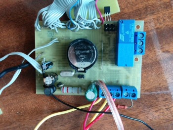
The photo was taken during the debugging of the device, so there are old K-Line adapter and ULF boards here. New boards were installed later, without completely removing the device from the car panel, so such detailed photos No. But the general meaning, I think, is clear.
An IDE cable was used to connect the display. It is much more convenient to solder it than ordinary Chinese, because. the wires in it are single-core, as a result of which you don’t have to worry that when soldering, the “hair” will bend and short to the adjacent wire. Plus it has more durability. I do not recommend using Chinese multi-core cables. Last resort MGTF. Initially, an outdoor temperature sensor was ordered from the Chinese (a metal sleeve with a wire), and it turned out to be really waterproof. But at the very first frost, one interesting and unpleasant property of the street sensor was discovered. When the temperature drops to -1 degrees, he refuses to respond to requests from the MK. Therefore, later I made a waterproof sensor out of an ordinary one, simply by shrinking the leads and the sensor itself with heat shrink, and filling it on both sides with sealant. At the same time he moved it from under rear bumper(I got very hot from the backlight of the number) under the trim on the rear triangular glass (there, while driving, it heats up by a maximum of 2 degrees). After that, the sensors began to work stably at any temperature. Also, when connecting a long wire for the sensors for the first time, I had to reduce the resistance of the pull-up resistor from 4.7K to 1K, otherwise the sensors refused to work. The connection is made by twisted pair.
The whole thing is installed instead of an ashtray near the gear knob. To do this, the front panel was cut out of plexiglass about 3 mm thick. and covered with a carbon film (at least the Chinese call it that). Because the surface in the area of the ashtray has a curve, then protrusions are made of acrylic resin on the side and turned along the curve of the panel. I did it very simply, first I cut out blanks from cardboard, then glued them onto plexiglass and smeared the joints with plasticine, after which I simply poured resin into it and, after drying, processed it with sandpaper, giving it the final shape. As a result, from above and below the front panel is tightly inserted into the groove of the ashtray, and on the sides it is adjacent to the panel. The sides are covered in carbon fiber.
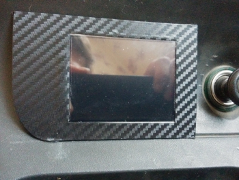
Inside, all electronics are covered with a native casing from the ashtray. The memory card and Micro USB connectors are brought out under the decorative overlay of the gear knob (soft). The light sensor is placed on top of the panel in the airflow grille windshield, because must be exposed to street light.
A 3V coin cell battery is responsible for the smooth operation of the watch. It is unlikely that you will ever have to change. because most of the time the circuit runs on battery power. The circuit is powered by a DC-DC converter on the popular MC34063 chip. Voltage 3.3V. The current consumption is small, the microcircuit does not heat up and works without an external transistor. The circuit starts even on a dead battery, when the dashboard does not start at all.
Now let's look at how this whole thing works.
While no one touches the device, it is in standby mode. The screen is off and only the temperature sensors are polled once a minute to keep statistics. You can turn on the device in two ways:
The first is to touch the screen. This will turn on the backlight and display the main screen. The presence of temperature sensors is checked each time the screen is turned on, and if there is no connection with one of them, N/A will be displayed instead of the temperature.


In this mode, all settings are available, but, of course, data from the ECU is not received and displayed. If within 20 seconds no actions on the part of the user are carried out, the device switches back to standby mode.
The second is to turn on the ignition. In this case, the splash screen will be displayed first and the power-up sound will be played (if the sound is enabled in the settings), and after 8 seconds, the connection to the ECU will be made.
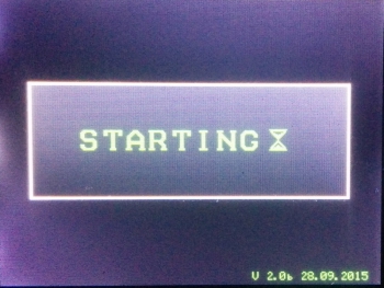
This delay is not accidental. Firstly, after power-up, the ECU sends garbage to the line for several seconds (at least my BOSCH does just that), and secondly, an attempt to connect to the ECU during or immediately after starting the engine ended in problems with starting the engine. He either did not start at all, or stalled immediately after the start. Then the Home screen will turn on. If communication with the ECU is established successfully, the read data will be displayed, otherwise zeros will be displayed and the device will periodically try to establish a connection with the ECU.

Now let's take a closer look at the Home screen. As you can see, it consists of two zones. The first zone is designed to display various information in the form of a table. Let's decipher what's there:
- MAINVOLT. - voltage in the on-board network.
- TEMP. INT. - temperature in the cabin.
- TEMP. OUT. - outside temperature.
- ENGINE TEMP. - engine temperature.
- ENGINE RPM - engine revolutions per minute.
- SPEED - movement speed km/h.
- FUEL RATE - instantaneous fuel consumption in liters.
All values, except for the temperature in the cabin and overboard, are read from the packages requested from the ECU. Negative temperatures (including the engine) are displayed in blue (the minus sign did not fit there). To display the revolutions, 4 digits are also required, which do not fit in the allotted space. Therefore, it is done as follows. When the value is less than 1000, the color of the numbers is light blue, if the value is greater than 1000, the color changes to green, the units of revolution are not displayed (128 = 1280-1289 rpm), and when 3500 is exceeded, the color of the numbers turns red. The color of the speed also changes, when the mark of 130 km / h is reached, the numbers turn red. In the right upper corner The screen displays the time.
The second zone contains status icons. From left to right:
Some of the icons are clickable and open additional information screens. These are: Temperature overboard, Fuel consumption, Time, Filter replacement indicators. When you click on the icon (well, or directly on the numbers related to it) of the expense, a statistics screen opens. The Maximum, Minimum values are displayed here. For outdoor temperature, it will look like this:
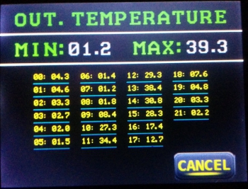
The table of temperatures recorded for the day is displayed here. Resetting occurs at 00:00. Pressing the CANCEL button will return us to the Main screen.
Clicking on Time will open the trip statistics screen:
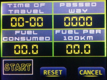
It displays TIME OF TRAVEL, PASSED WAY, FUEL CONSUMED and Consumption per 100km. (FUEL PER 100KM). There are 2 modes of operation. As long as the START button is not pressed, the data is reset 5 minutes after the engine is stopped. If you press the START button, then the statistics will continue until the RESET button is pressed (hold for 2 seconds), even after the engine is turned off.
Clicking on the filter replacement icon will open the following statistics screen:
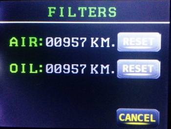
The mileage since the filter was changed is displayed here. Holding the RESET button resets the readings for the corresponding filter and is done after each replacement. The calculation of the distance is based on impulses from the speed sensor.
This completes the functions of the Home screen. Now let's look at the settings screen, which is called up by pressing the Settings button in the lower right corner of the screen. It looks like this:
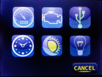
Here you can see 6 icons. Each of them opens its own settings item. Let's consider each of them in more detail.
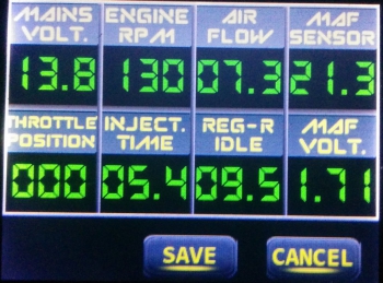
Here we see:
- Mains voltage (MAIN VOLT.);
- Turnovers (ENGINE RPM), color designation the same as on the main screen;
- Air consumption (AIR FLOW);
- Mass air flow sensor (MAF SENSOR);
- Throttle position (THROTTLE POSITION);
- Injection time (INJECT. TIME);
- XX position regulator (REG-R IDLE);
- The voltage on the DMRV (a very useful parameter, allows you to find out the health of the sensor) (MAF VOLT.).
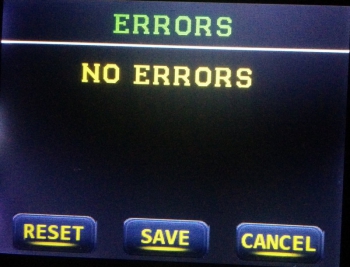
I have no errors, so the screen is blank. Error codes can also be saved to a memory card by pressing the SAVE button. This will be a text file called errors.txt. In addition, errors can be reset by holding the RESET button. Quite a useful feature, the ECU does not always reset errors after replacement faulty sensors. If the reset was successful, a corresponding notification will appear on the screen, after which the errors will be read again.

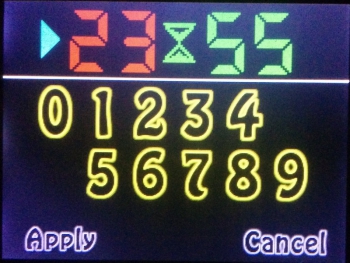
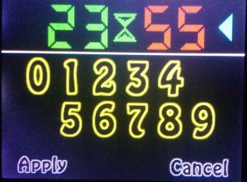
Installation is carried out by pressing the numbers. The value that changes in this moment, indicated by an arrow. The choice of the parameter to be set (hours/minutes) is carried out by pressing the same hours or minutes. Apply settings by pressing the Apply button.
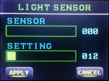
The top bar shows the current light level. And the lower one is used to set the level at which the headlights should turn on. In this case, if the movement has just begun, then the headlights turn on immediately, and if the car has already moved before the light level drops below the specified level, then the inclusion will occur only after 15 seconds. If the car is stationary (wound up, we warm the engine), then the headlights will not turn on. The determination of the start of movement occurs both according to the speed sensor and according to the ECU. That's why given function will work even if there is no connection to the ECU. Switching off occurs either 5 seconds after the engine stops, or by pressing the headlight mode control button on the main screen. Saving settings by pressing the APPLY button.
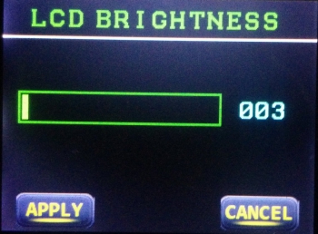
There is only one scale. When adjusting the brightness, the level changes immediately, but if you do not press the APPLY button, the previous value will be returned after exiting. Once set, the display brightness will automatically change in proportion to the current light level, based on the level set by the user.
This concludes the various menus and settings. only a few features remain:
- Headlight control. If, after turning on the engine, the machine is standing still, then the inclusion will occur after 2 minutes. If movement has begun, or the engine temperature has reached 40 degrees or more, the inclusion will occur immediately. Shutdown occurs one minute after the engine stops.
- Salon lighting control. When the door is opened, a gradual increase in the brightness of the lamp begins, which lasts about 13 seconds. If the door is closed, then the brightness will remain at the level to which it managed to reach while the door was open. Further, if the car is stopped, then after 10 seconds the brightness will begin to decrease (the rate of decrease is 2 times lower than the increase). If the movement is started, the lamp will be extinguished almost immediately.
- Sound notifications. There are 3 such notifications in total. One of them is the sound of the splash screen, the second is the sound of the headlights / dimensions notification, the third is everything else.
- Light notifications. There are 4 of them. The first - the LED lights up when you click on the screen, the second - a notification about turning on / off the headlights / dimensions (2 flashes with an interval of 0.5 seconds), the third - a notification from alarms (5 flashes with an interval of 0.2 seconds) and the fourth is a notification about the standby mode (one flash with an interval of 5 seconds). This type of notification is not disabled.
This is where the current functionality ends. Now let's look at some technical aspects of the device.
- Graphic arts. The entire interface is presented as regular images in BMP format. RGB565 color space. The pictures themselves must be mirrored vertically. Stored on the memory card in the /sys directory.
- Sound. It's even easier with sound, there are ordinary WAV files, mono, 8 bits. The sampling frequency does not really matter, the program provides auto-tuning. The duration of the power-on sound is no more than 6 seconds, and notifications are no more than 2 seconds. Stored on the memory card in the /sys directory.
- Memory card. Regular Micro SD (or SD) card formatted in FAT/FAT32. I checked both 128MB and 8GB - they work. The map stores both interface elements and all device settings (/sys/settings.bin). Therefore, each time the card is turned on, a search is made for the card, and if it is not there, then a message is displayed:

To start, you should insert the card and click on the warning. After that, the system will start working.
Display calibration. The first time the device is powered up, the sensor needs to be calibrated. It is carried out very easily, you need to click in the center of the crosshairs that appear on the screen. There are 4 such points in total.

After the calibration process is completed, the values will be saved to the memory card in the /sys/touch.bin file. Accordingly, deleting this file will entail recalibration.
In general, the interface turned out to be very smart, switching occurs instantly. A short video at the end of the article demonstrates his work. The fonts in the firmware are only English, the words are shorter, it is easier to fit them on the screen. There are 3 fonts in total, one of them is only numeric for displaying parameters, and two are alphanumeric. One with large characters, the other with small ones.
The firmware is written in the C language in the Eclipse environment, the source codes are attached. About 1/5 of the MK memory is occupied, so there is still room for improvement. I also attach the files necessary for the operation of the device. The device itself has been working in the car for more than a year and is quite good. It worked both in summer at 40-degree heat and in winter at -20. No problems have been identified. The display does not react in any way to frost, there is no slowdown in the output. I will try to post firmware updates in the comments. In principle, it’s not a problem to add support for several communication protocols with the ECU and at the same time load them from the memory card (we write commands in a text file, throw them on the card, and then the MK deals with them on its own). So far, work has been tested with the BOSCH ECU on a car manufactured in 2001. That's all for me.
List of radio elements
| Designation | Type | Denomination | Quantity | Note | Shop | My notepad | |
|---|---|---|---|---|---|---|---|
| Main board | |||||||
| U1 | MK STM32 | STM32F103VC | 1 | Search in Chip and Dip | To notepad | ||
| U2 | DC/DC switching converter | MC34063A | 1 | Search in Chip and Dip | To notepad | ||
| Q1, Q2 | bipolar transistor | BC857 | 2 | Search in Chip and Dip | To notepad | ||
| Q3, Q5, Q7, Q8 | bipolar transistor | BC847 | 4 | Search in Chip and Dip | To notepad | ||
| Q4 | MOSFET transistor | BSH103 | 1 | Search in Chip and Dip | To notepad | ||
| Q6 | MOSFET transistor | ||||||
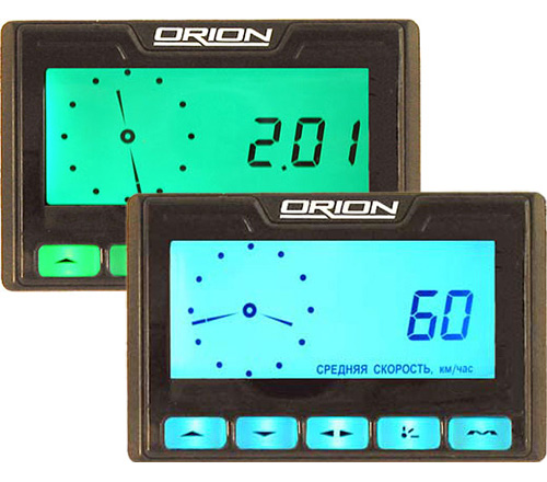
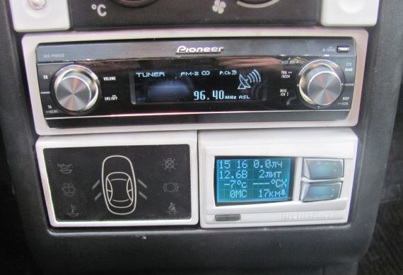
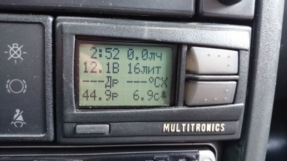
Many drivers are interested in the instructions for the standard on-board computer VAZ 2110 and 2112. After all, this device is installed in almost every car of these models, but it does not always work. This is due to some versions of the BC on these models. In many cases, this device only works as a timer. This may happen due to a shortened firmware or a version without output for connecting the K-channel. In any case, it is important to know how to properly use this device, from installation to operation. Indeed, otherwise, the BC will not be much more effective than conventional watches.
What is it for?
Instructions for the standard on-board computer VAZ 2110 and 2112, can tell you what this device is used for. In fact, this BC is not very functional, but at the same time, it can still make life much easier for the owner. The standard firmware includes the following features:
- Mileage calculation;
- Average fuel consumption;
- Calculates power reserve on balances;
- Movement speed;
- Time and temperature outside.
Self-diagnosis
It is desirable that your BC has the ability to diagnose problems with the engine. Some versions of the device do not have this capability, in which case their firmware should be replaced with a more functional one. After that, the “self-diagnosis” mode will be available to you, which will make life much easier. The check is carried out with the Check Engine light on. Depending on the model, the transition to the diagnostic mode can occur in two ways:
- If there is a basic BC, it is necessary to hold down the daily mileage reset button, and at the same time turn on the ignition;
- In some models, when you press the watch button, you can enter the diagnostic mode.
Installation. As already mentioned, not all 2110 and 2112 machines have an on-board computer with full functionality. In this case, it is advisable to buy and install a fully functional device. It is not difficult to do this. It is enough to connect the wires correctly, according to the diagram attached to the instructions.
Function adjustment
For the full operation of the device, it must not only be installed, but also configured. If this is not done, then some functions will not work correctly, which will reduce the efficiency of using the on-board computer. When "overflow" of some indicators, the counters are reset. The BC is set up in the following way:
- The clock is set using the "current time" button. Can be put exact time, date, and set an alarm. Setting the time contributes to a more correct calculation of the trip time;
- Brightness can be adjusted in two ways. If the side lights are on, you can adjust the brightness using the instrument lighting control knob. With the lighting devices turned off, in the "Travel time with stops" mode, press the "4" button. In this case, you will see the corresponding icon and the brightness level indicated by the number.
- Adjust the indicator, then press the "4" button again;
- Calibration of the gas tank is carried out as follows. To begin with, all gasoline is drained, after which the “4” button is held for 2 seconds. "0" should appear. Next, add 3 liters of gasoline and wait until the meter calms down. In some cases, you will have to enter the volume manually. The procedure is performed up to a volume of 39 liters;
- Optionally, you can set the mode top speed. To do this, enter the "average speed" mode using the appropriate buttons, set the speed threshold. We exit this mode. Now, when you reach a certain speed, you will hear a beep.
flashing
As already mentioned, the standard on-board computer firmware does not have many useful features. It is treated by replacing one program with another. But, there is one small downside. Reprogramming is possible only if Win 95-98 is available on the computer; it will be impossible to do this on all other operating systems. There are 2 ways out of this situation:
- Installing a virtual machine on a computer with the required Windows;
- Soldering the on-board computer processor.
- Which method to choose depends on your skills and abilities.
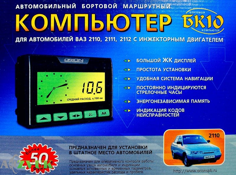
Many car owners are tormented by the question of whether it is worth installing on your car. Most of all, this applies to those who plan to install a computer on a VAZ 2110, 2114. Today you will learn what it is, why it is needed, and how to install an on-board computer on these cars.
What is an onboard computer?
To be as brief as possible, such a device is a panel that displays the most important values \u200b\u200bfor the driver. These include:
- Travel speed
- Coolant temperature
- Temperature outside the car
- Speed
- The volume of fuel in the tank, and for what mileage it can be enough, as well as many other quantities that, one way or another, may be needed during the movement.
The main feature of on-board computers is that they display the most up-to-date data in a given period of time, that is, they constantly change, depending on the speed of movement, the distance traveled and the effort of pressing the gas pedal.
![]()
Basically, a regular on-board computer is installed only on luxury versions of VAZ 2114 cars, and in the "dozens" they simply do not exist. Therefore, many drivers are trying to supplement this shortcoming on their cars by purchasing and installing an on-board computer on their own.
What can it be useful for?
- First, the on-board computer can be a very useful diagnostic tool for an injection car. There are such malfunctions that it is unrealistic to determine visually or by the “poke” method. In this case, diagnostics come to the rescue, which, using encrypted errors, indicates the corresponding malfunction.
- Another use case for the on-board computer is fuel consumption and remaining quantity data. For example, if you are in a hurry and cannot make the right decision whether to refuel now or do it later, then the on-board computer can also help, which will calculate everything and tell you how many kilometers you can run out of gas.
The functions of many on-board computers may include controlling many of the vehicle's systems, such as the ignition system, in order to change the timing and build your car for a different octane number of fuel.
And many other functions such as clock, voltmeter, etc.
It is worth noting that if you are one of those specialists who already knows your car well enough, then an on-board computer will only be superfluous for you. It is most suitable for a novice driver or someone who simply does not have time to monitor the condition of their car.
How to choose an on-board computer for a VAZ 2114 and 2110?
Choosing a computer is a responsible matter, but not difficult. In this case, you need to remember a few simple tips. First of all, you need to know that there is no clear selection criterion, because the operation of the on-board computer will depend on yours.
The presence of certain functions will affect the price in direct proportion. In addition, the accuracy of the readings also affects the cost of the device. Therefore, it is clearly not necessary to save on the on-board computer.
The cost of on-board computers ranges from 1500 to 4000 rubles. At the same time, if you order them in online stores, then there is a chance to buy such a device at a price much lower.
How to install an on-board computer on a VAZ + Video
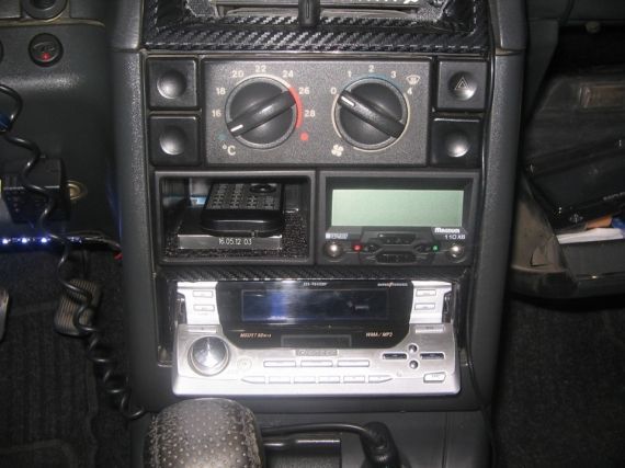
First you need to find a place to mount the device. In this case, the VAZ 2114 has an advantage, in which such a place has already been provided. It is located under the buttons on the instrument panel and above the central air ducts. First, remove the special panel and cut out all the necessary mounting holes in it. Install the on-board computer, connect it to the computer and put the panel back.
The VAZ 2110 already has a small regular on-board computer that displays the parameters in the form of symbols. In its place, you can install a more advanced device and connect it to the controller. The dimensions of the device, which are selected taking into account the standard computer, will help you with this. If you remove the clock from the panel, you can install a wider device with big set functions.
This is how you can install on-board computers on the VAZ 2110 and VAZ 2114. As you can see, there is nothing complicated about this. As always, the only question is the price of the device